by
by In my neverending quest of improving my homemade PCBs, I discovered that adding a soldermask to my boards is actually not a hard task, thanks to a relatively simple process that involves UV-curable paint. Now, while using the sunlight as a UV source should work just fine, I decided that it was time to build a proper UV exposure box. Winter is quickly approaching and I’m not too fond of the idea of having a variable-intensity light source (the sun) that would make the process (and end result) completely dependent on how good was my estimation of the time required to properly cure the paint given the weather of that particular day.
A UV Box would also allow me to experiment with UV-based transfer methods for the PCB etching process as well, so it was definitely time to build one.
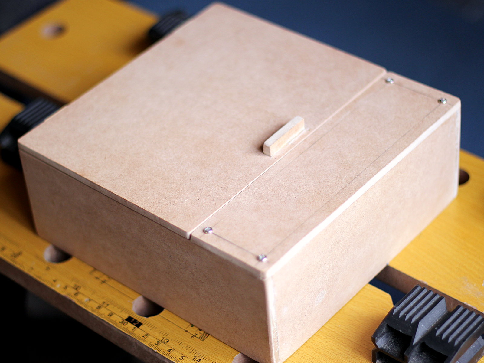
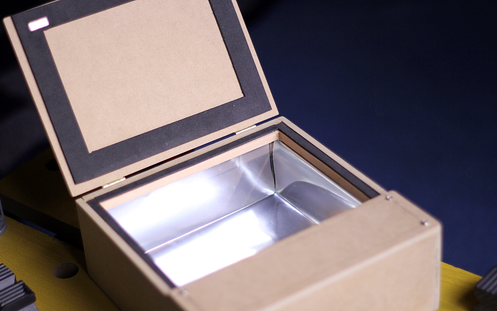
I started with the structure, which I made from 5.5mm-thich MDF, easily obtainable from my nearest hardware store. The box needs two sections: a lid-covered compartment where the exposure “bed” will be, and a control “panel” under which the electronics will be installed. Everything should be easily removable for repairs and debugging.
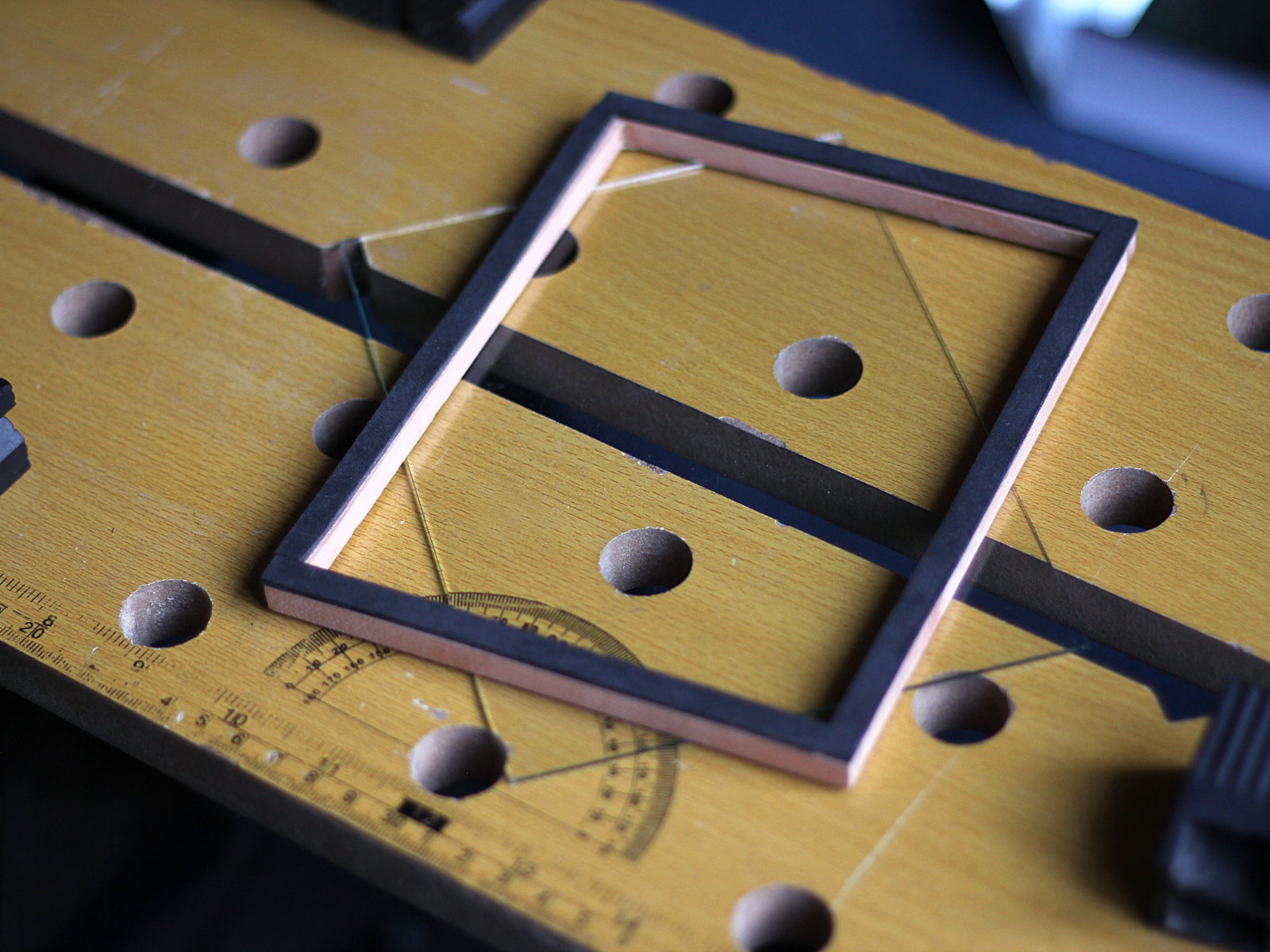
For the exposure bed I wanted to use a small piece of glass I salvaged from a picture frame (from which I made something else), so I based the design around its size (around 17x13cm) , and also calculated the required height of the box from the light emission specs of the UV LEDs I purchased. According to my own tests -and several online sources- they have a cone of light barely 20-22 degrees wide, and I wanted them to be 1.5cm apart (so I have space to mount individual resistors on the PCB). To ensure intersection between the cones of light of adjacent LEDs, the board needs to be held 0.75cm/tan(10°) = 4.25 cm above the LEDs. To achieve this number comfortably, I designed the box so the PCB with the LEDs can be installed 5cm under the glass (using 5mm PCB spacers).
If after assembling the whole thing I don’t get a relatively uniform light over the exposure bed, I will consider adding a diffuser under the glass.
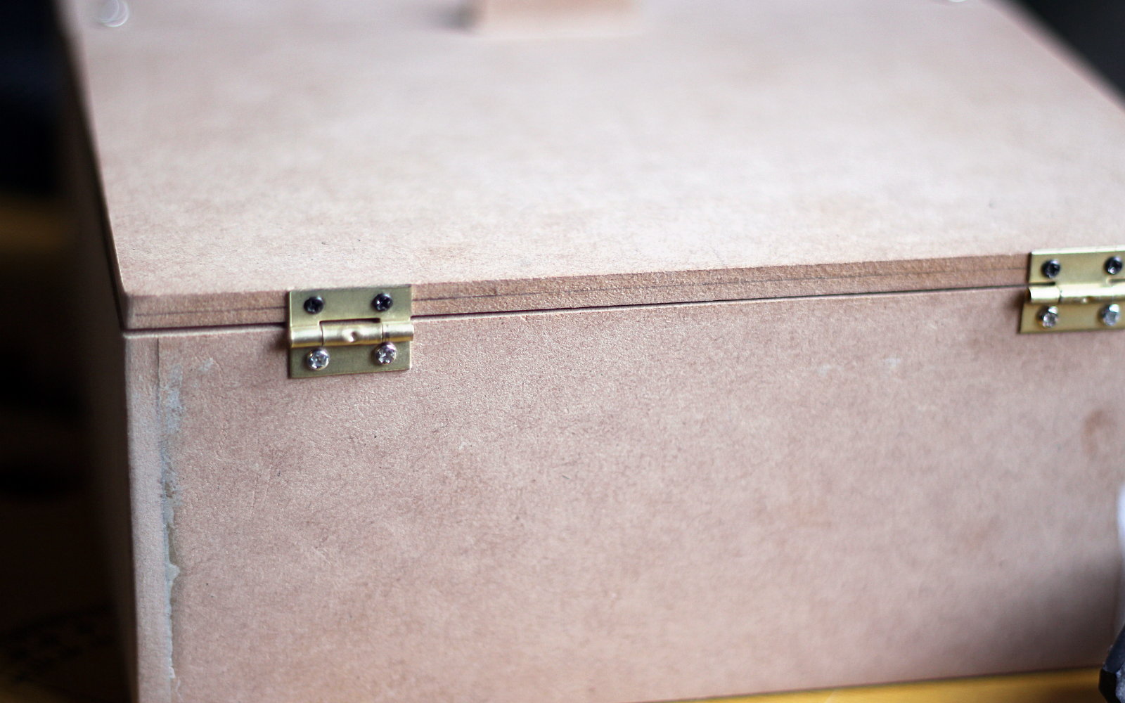
The hinges were installed after everything was measured, and several other elements were placed inside the box, but I definitely had to do some tests on spare pieces of MDF to determine the best way of securing them to the lid. I ended up using small screws that don’t damage the MDF if you carefully drill small holes for them beforehand.
Of course you don’t want UV emissions to leak once the box is closed so I ran a few tests and found out that EVA foam is a surprising good material to “seal” the exposure chamber. I know this because I actually dropped a bright flashlight inside the box, placed the lid on top with a layer of black EVA foam underneath (hinges were not installed yet), and then turned the lights off, searching for spots along the edge were light would shine through, and I found none. So having done that test, I secured a layer of EVA foam to the exposure bed frame using double-sided adhesive tape, and cut a thicker frame of the same external size. This was later glued to the lid, but only after the hinges were installed, to ensure perfect contact between the two pieces of foam with the lid closed.
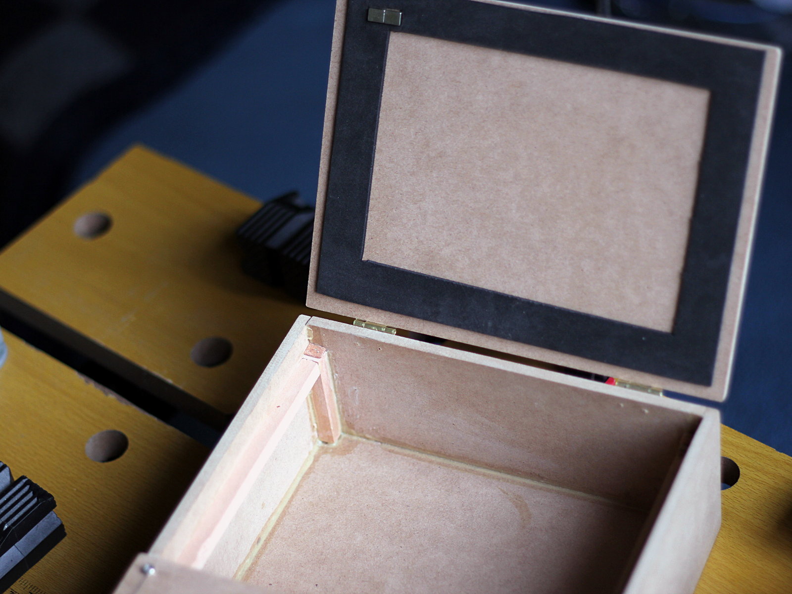
You will also notice in the picture above that there’s two small neodymium magnets under the lid, embedded in the EVA foam frame, and I’ll explain their purpose in a second.
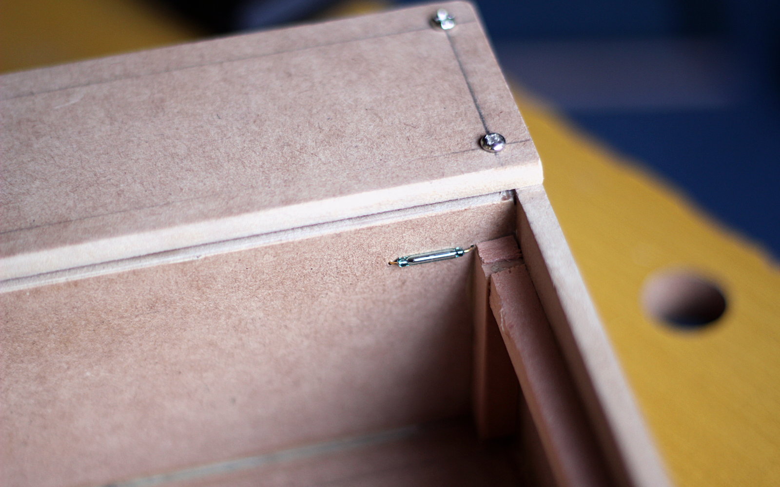
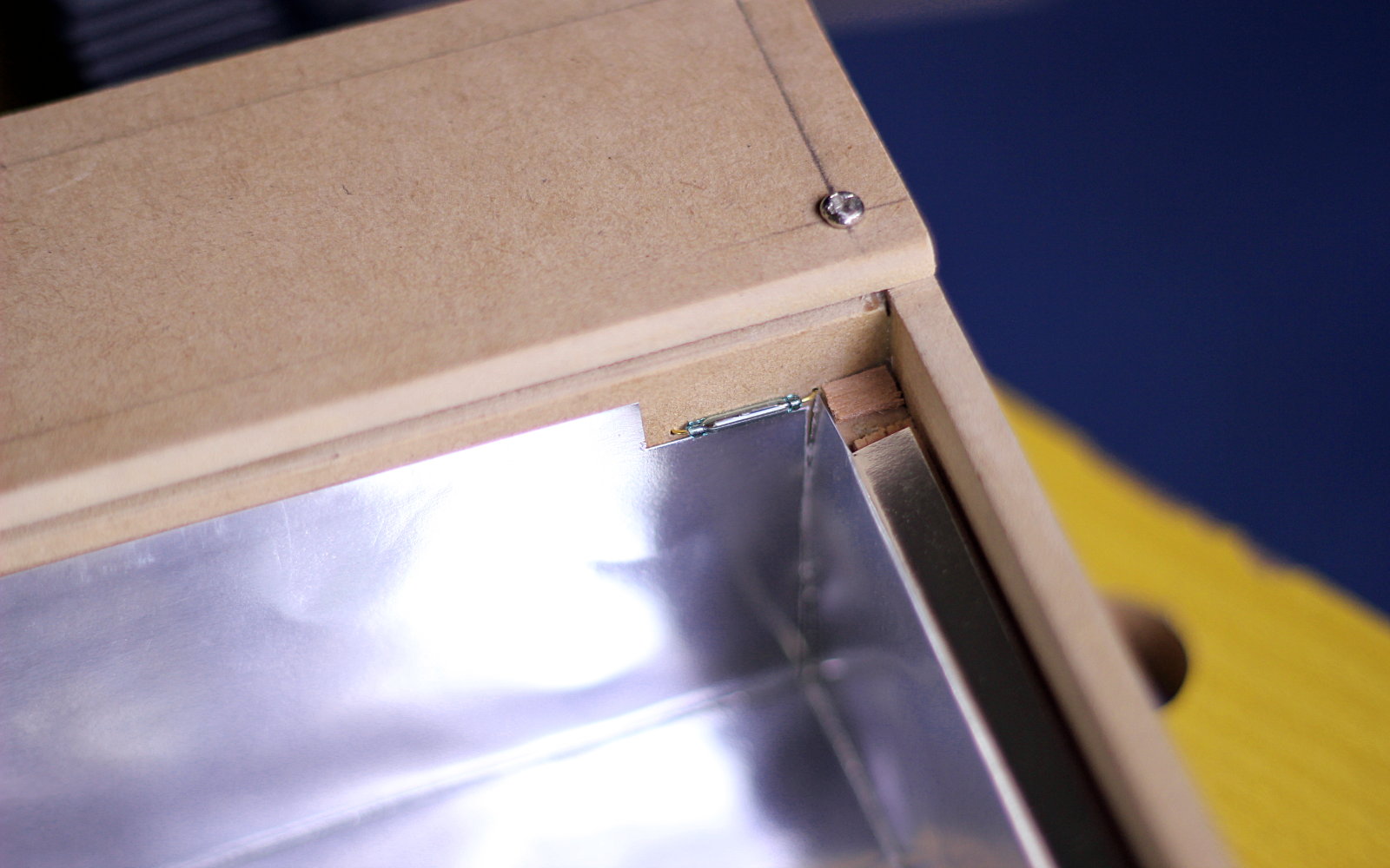
A reed switch was installed in a corner between the exposure chamber and the control section of the box. This is a component that acts like a switch that closes when there’s a magnetic field nearby, and it’s completely covered by the frame when everything is installed. The small magnets I placed under the lid were obtained from a broken CD Drive, and are quite strong.
Once the lid is closed the magnets sit right in the inner corner of the bed frame, close enough to the reed switch to activate it, but since they rest inside the frame, they don’t compromise the light-proof qualities of the box.
With this mechanism I can detect if someone accidentally opens the box in the middle of the process, and I can pause the timer and turn the UV LEDs off as a safety measure, as UV light is not good for the eyes.
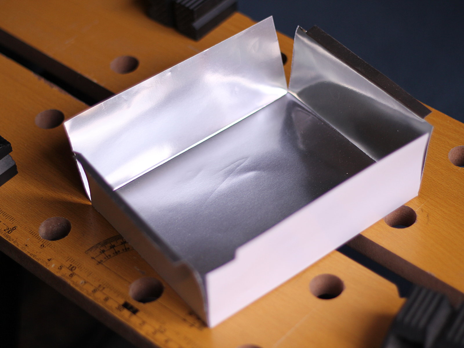
I also made a “reflective” insert for the exposure chamber using folded silver card stock. I don’t know if I will end up using this, but In theory it should help redirect UV light that would otherwise hit the inner sides of the box, towards the surface of the exposure bed.
I have not done the control logic nor the UV LED board, but I’ve made the PCB model for the UV panel, and it will be a 7×10 matrix of UV leds with individual current-limiting resistors. Each LED will draw 18-20mA so the whole 70-led panel will draw at most 1.4A.
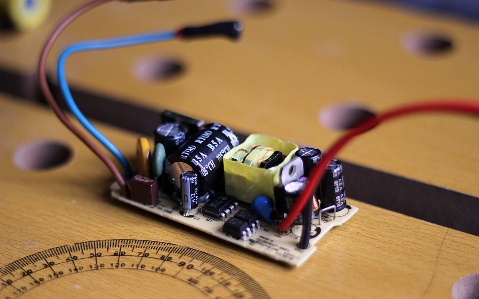
To power the whole thing I got a 100V-240V AC to 5V DC 2A switching power supply from ebay, which according to my tests with a dummy load delivers stable 5.2V DC up to 1.80 A with no problems. At 1.82 A the overcurrent protection kicks in, and voltage drops to 0. I’m a little disappointed that it’s not 2A as advertised, but stable 1.8A should still be more than enough for my purposes.
The supply kinda looked “recycled” from something else, which to be fair I don’t mind. It works with our 220VAC (so the input range is probably accurate) and seems reliable.
More importantly, it has protection features (overcurrent, overvoltage and short-circuit according to the listing) which is more than I would have expected for the price (less than $2 USD). I can only attest to its overcurrent protection, but that already is impressive on its own. It also sits nicely in the control compartment of the box, which is around 4.5cm wide inside.
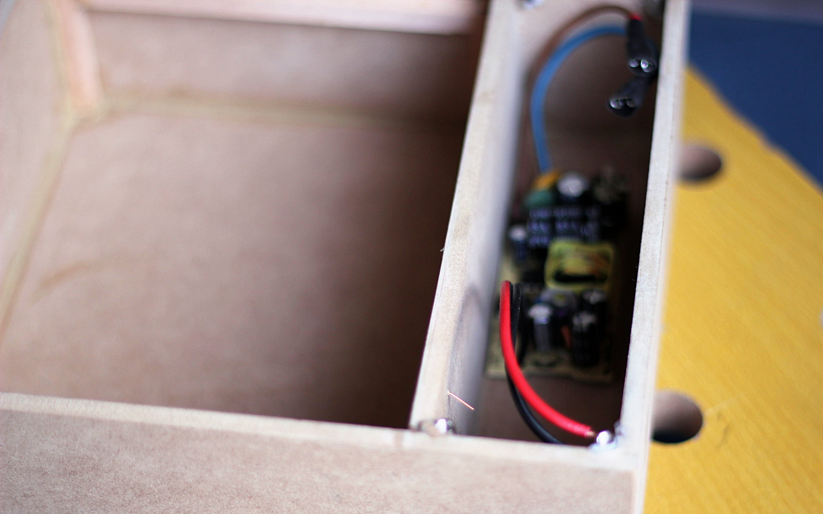
In the picture above you can also (barely) see that I glued M3 PCB stands to the corners of the compartment using 2-part adhesive. With that I have easy access to the circuitry for repairs. I haven’t drilled the holes for the AC socket (which is still yet to arrive) nor the control PCB, display and buttons on the panel (which I haven’t made yet), but that’s the next step.
It may take a couple of weeks before I can post “Part 2”. I still need to design and make the PCBs for the UV LEDs and the control circuitry, and I have to wait for the AC socket to arrive. But so far I’m quite happy with the progress I’ve made with this.