by
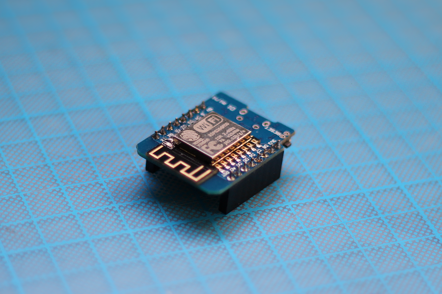
by You don’t see them around that much anymore, but a few years ago the ESP-01 modules took the world by storm as quick “serial to wifi” bridges for microcontroller projects. With a few serial commands you could quickly connect even the most basic microcontroller to the internet over Wifi!
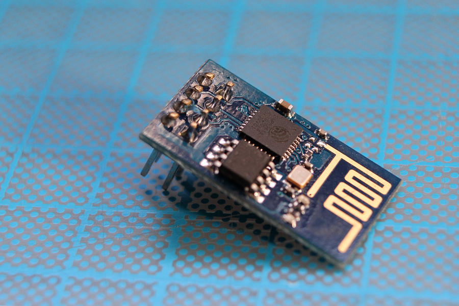
While they served their intended purpose rather well out of the box (as “wifi modems”), It didn’t take long before the community realized that these small modules were full programmable units on their own, with a powerful processing unit and plenty of memory for many applications. They did not require a “host” microcontroller to do useful stuff, and their factory firmware could be changed to something else.
Fast forward to a couple of years from that, and we currently have both official and unofficial SDKs for their ESP8266 core and a number of interesting projects that use them. One thing that has changed, though, is that ESP8266 modules are now commonly seen as part of “Arduino-like” boards, that include all the programming and interfacing hardware you’d need to write code for these devices on your computer and upload it via USB, and have many more I/O pins that the “archaic” ESP-01 modules offered. Arguably one of the most popular and widely-used designs right now is the Wemos series of boards.
Now, what the new boards do (that the older ones didn’t) isn’t rocket science. Technically speaking, making the ESP8266 core enter “programming” mode isn’t particularly hard. You only require to provide +3.3 to a certain pin, pull another pin to ground, and reset the device. Once that sequence is done you can reflash the firmware with a standard Serial TTL interface. Newest designs do all of this for you, but if you own several old ESP-01 devices like I do, and you want to update their firmware, or use them as something different than a Serial-to-Wifi bridge, then you’ll need additional circuitry.
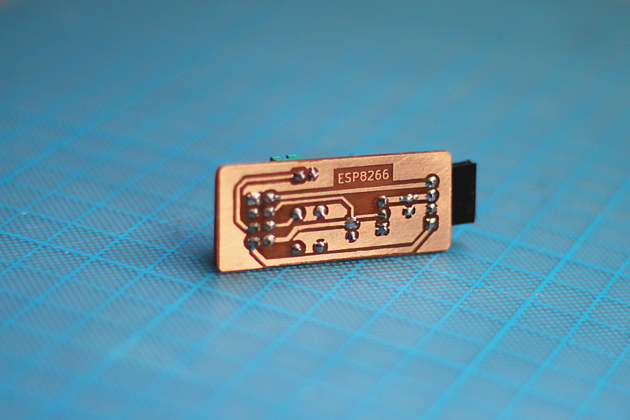
To update mine more conveniently I made a very simple board with the needed switches and signals, that only requires a standard USB-to-TTL adapter to work. Please bear in mind that the ESP8266 core is a 3.3V device, and my design assumes the RX line of the ESP-01 board is 5V-tolerant. In my experience with them, this seems to always be the case, but I would advise you to double check first if yours is “5V-ready” before building or using this circuit.
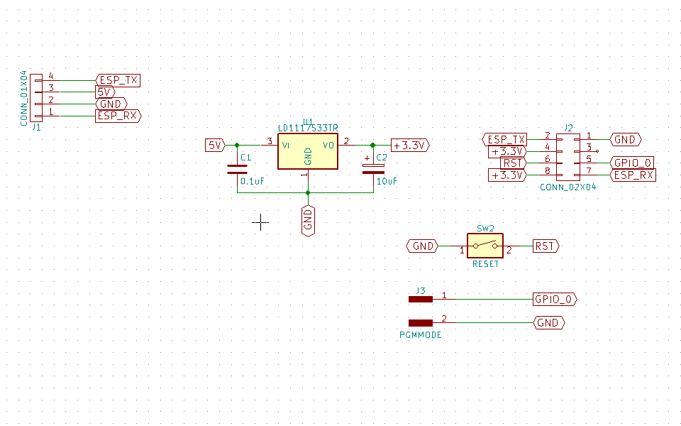
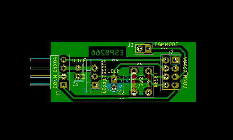
You’ll find all the CAD files (in KiCad format) and SVGs of the PCB stencil and soldermask in my Git repository for electronics projects.
To program a ESP-01 board with this adapter, you’ll need to short the J3 jumper (which enables programming mode) and press the RESET button when the IDE or your re-flashing tool is ready to upload the new firmware.
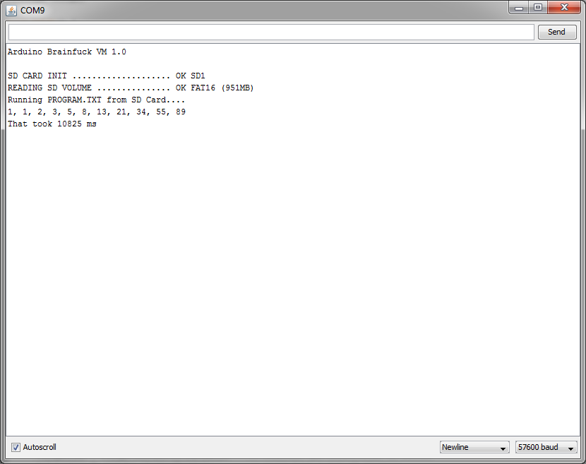
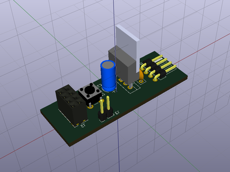
I have successfully used this adapter with all my ESP-01 boards, reflashing the firmware from the Arduino IDE, the official ESP8266 flashing tool, and Visual Studio Code + PlatformIO.
Here’s the finished product; Quite a handy thing to have, in my opinion.