 by
by 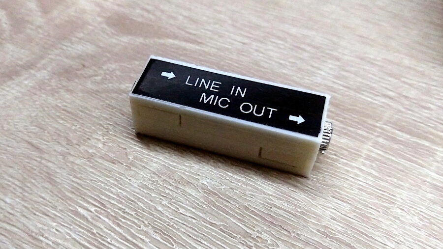
Tape recorders, computers and capture cards all seem to be happy to accept a microphone input for adding audio or voice-overs, but very few have a “line input” to overlay music or any other “strong” signal source instead.
While you can -in theory- connect a sound source there (at your own risk) you will find that in most cases you will get pretty distorted audio. This is because microphones normally work at a much lower signal level than regular “line” in/out audio, and have a DC offset to enable simple electret microphones to work with them, which is what most passive headset/desk mics actually are.
If you want to properly connect something there that is not a microphone, you need to (at the very least) attenuate the signal, and hopefully get rid of the DC offset.
Audio attenuator “pads” exist for this kind of use case, and it’s not hard to build one yourself. This page compiles a few options for different attenuation settings and use cases. For my needs I picked the one with the -20dB and DC-offset removal.
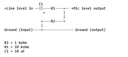
The circuit looks like this:
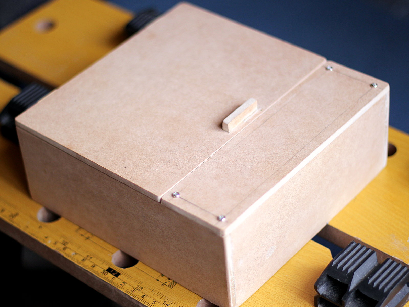
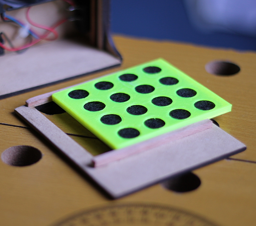
I free-form soldered this circuit and tested it on my computer, and seemed to work fine, so decided to build a small enclosure for it and 3d-print it. As usual, I’ve uploaded the model to Thingiverse.
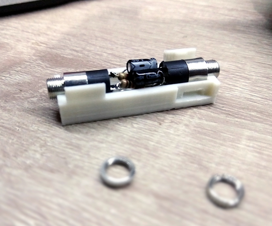
The small case should be able to accommodate most attenuation circuits, so you can build yourself a set of different attenuators for all your audio needs.


chat gpt wants to put a 500K ohm for R1 and 3.3K ohm for R2 and a 100Nf ceramic cap to go from a line 100 ohm output to a 1M ohm mic input. the 100nF is good enough for above 3,16 HZ so… really confused, I see nobody using 500K ohm resistors in such a circuit. even after saying that it persisted in not going below 47K. is says that R1 is for the attenuation and R2 for the imbalance or something.
I wouldn’t trust ChatGPT with circuit design, at least not right now. This circuit, however, is basically a voltage divider (where the attenuation will be proportional to the ratio between both resistances) and the capacitor is for DC-blocking. There’s no resistor for balancing here (as far as I know). Now, while in theory you “could” use bigger resistors as long as the ratio is right, in practice these resistors will also have to deal with the input and output impedance of the connected devices and their actual capacity to “drive” loads (i.e: source current). The resistances picked should allow a reasonable amount of current to flow, but not enough to bring down or drown the line voltage. Now, the frequency response (for that specific value of capacitor) is an interesting question. I don’t know enough about designing attenuators (or I wouldn’t have needed to look up already designed circuits :D) but my understanding is that the capacitor will act as a DC-blocking filter in combination with the input and output impedances, so its frequency response will depend on them as well, not only the capacitor value.