 by
by Background
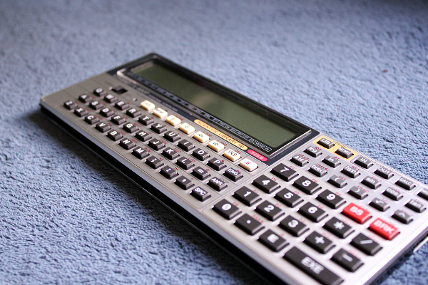
Back in the ’80s, Casio produced a line of calculators that was sold and advertised as “pocket personal computers”. This branding started with the PB-100 I believe, but the device concept started with a previous model, the FX-702P, produced in 1981.
While by today standards that claim seems a bit of an stretch, it held quite a bit of ground back then. These calculators featured a BASIC interpreter built-in, and internal memory to store user programs. They also featured a proprietary port/interface that allowed some Casio peripherals to be connected to the device, like a printer or a cassette drive. Personal computers back then were not much more than that.
The FX-850P model released in 1987 -and other calculators that followed- were a significantly step forward since their peripheral options (via the Casio FA-6 Casio interface) included standard Centronics parallel port and RS-232 serial connectivity, both ports widely used in computer hardware.
The FX-880P, released in 1990, was (I think) the last device in this line of Casio personal computers / calculators, and was basically a FX-850P with 32KB of RAM (instead of just 8KB).
When I was a kid I used to see this calculator in store catalogs and magazines and always wanted to have one. Many years later, when I was old enough to purchase my own stuff, I was finally able to get one (second hand) in pretty good condition, and I still use to this day.
Standards
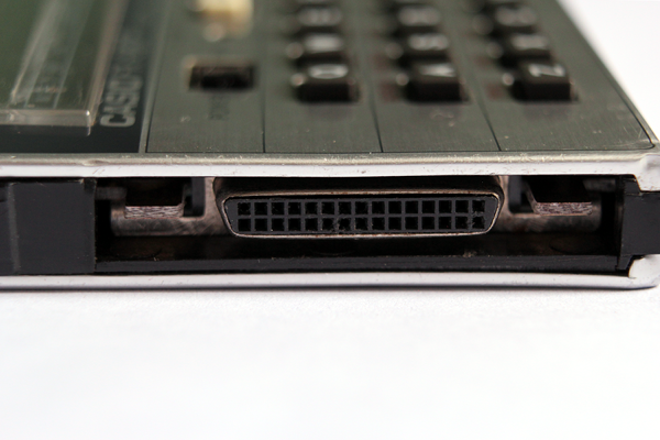
Despite providing fairly standard ports in their FA-6 interface, the connector used by these calculators was still proprietary, and included all the signals to communicate with the supported peripherals (although some voltage/level conversion and support circuitry was still required, and that was exactly the function of the FA-6 interface).
What was relevant to me was the RS232 port offered by the interface. This allows you to connect the calculator to computers, GPS loggers, modems, serial terminals, microcontrollers and an incredibly big number of other devices.
Years ago I found the schematics for a serial adapter for the computer, but since the connector was so weird I ended up with a bunch of components in a breadboard and some cables connected straight into the port in a very unprofessional and most-likely unsafe fashion. It worked, but it wasn’t something I could call a permanent solution.
I always wanted to make a serial interface for the calculator but the stupid proprietary connector was always the problem… until now.
A couple of months ago I discovered that while the general layout and shape of the Casio connector was proprietary, the space between the pins (1.27mm) was actually standard (a bit of an obscure standard, but standard nonetheless).
I got a couple of 2-row right-angle 1.27mm pitch headers from user tubemen88 on eBay. You just need to cut one to size (15 rows. 30 pins) and “move” the plastic stopper a bit to make the pins longer where the calculator goes.
So at least the connector part was solved now and I could worry about the circuit.
RS232 vs USB
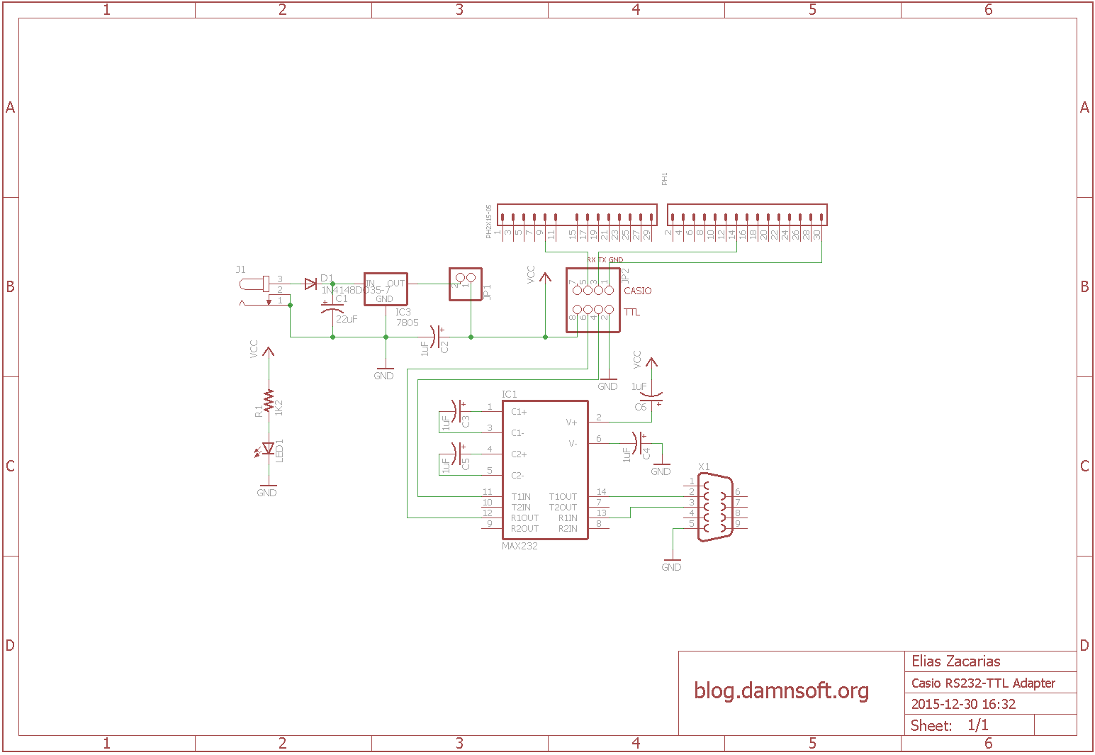
I no longer had the schematic I once used, but I remember it was basically a simple RS232-TTL converter. The pinout for this calculator is widely available online, but hey! here’s a copy in case the rest of the internet explodes and only my blog survives:
Converting a RS232 signal to TTL levels is fairly common practice if you are into electronics and microcontrollers, and it’s ridiculously simple thanks to ICs like the MAX232 from Maxim (or Texas Instruments).
But nowadays it’s also possible to build a USB-TTL interface using a FTDI FT232RL or similar, which would be actually simpler and would allow you to connect the calculator straight to the USB port of your computer.
Unlike USB (which has a 5V line), RS232 does not include a “power” line in the port, just signals and GND. Hacks and non-standard solutions aside, this is why every RS232 device needs to get power from somewhere else.
NOTE: The Casio port does have a 5V line though, but it’s too weak to power anything (or at least not the MAX232 and a LED according to my tests).
So I had to decide between USB and RS232 for my adapter: A USB board would draw power directly from the USB port and wouldn’t need a external power supply nor power-related circuitry. It would -however- be very limited in use, as it would only allow me to connect the calculator to a relatively modern computer and nothing else. Going RS232 would allow me to connect the calculator to old and new computers alike as well as standard RS232 devices, but it would be more bulky and would require not only a external power supply but also extra circuitry for that.
Despite my best efforts, I was unable to pick, so I decided to go with both… kinda.
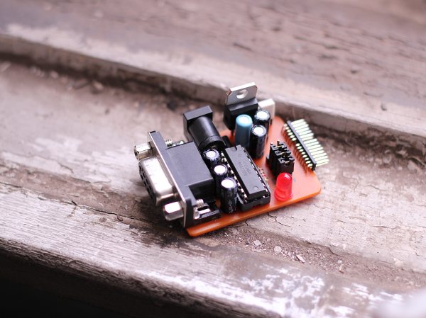
The Design
Since I needed to build a RS232-TTL converter + power supply combo why not make it flexible enough to be used in other applications and not only with these calculators? I could also expose the Casio port via a header in a way that would bypass the RS232 circuitry, allowing me to connect a standard USB-TTL adapter (if I wanted to directly connect the calculator to my computer via USB), or directly interface the calculator to TTL logic (like microcontrollers!).
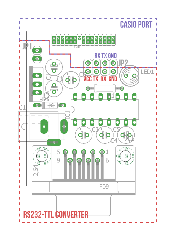
NOTE: For the Casio connector I modified a part from Piotr Esden-Tempski’s Eagle Libraries. I built a 30-pin part from his 1.27mm headers, and removed one pin from the resulting component so I could reach the pin behind easily in the PCB.
The board has 2 headers: JP2, which is a 2×4 header that exposes both the TTL side of the MAX232 and the Casio port, and JP1, which is a simple 2 pin selector that can be used to disconnect the power stage from the board in situations where you already have a 5V line in your circuit.
If you short the GND, TX and RX lines of JP2 with standard jumpers, and plug a 7-15V wall adapter (or a 9V battery) into the power jack, it becomes a fully functional RS232-Casio interface that will connect your calculator with any computer and RS232 device.
If you remove the jumpers from JP2 you can use the top row of this header to directly connect TTL signals to the calculator port, which would now be completely isolated from the RS232 circuitry. This means that you can connect stuff like USB-TTL adapters, microcontrollers, etc and no power adapter would be required as the RS232 circuitry is not used.
Similarly, you can use the bottom row of JP2 (which without the jumpers is disconnected from the Casio side) to use this board as a standard general purpose RS232-TTL converter for your circuits. External power is optional in this configuration; If the target circuit can provide 5V, no wall adapter is required, just connect the 5V from the target board to the VCC pin of the header and remove the jumper from JP1 to disconnect the power supply circuitry. If that’s not the case you can plug the wall adapter back to this board (and leave JP1 on) and now you have a 5V output that can also power your target device.
So in the end this is a sort of RS232-TTL + 5V Power supply combo, with an optional Casio port that can be disconnected from the rest of the board, allowing the use of each part of the circuit individually.
I decided to use a female RS232 connector so no exotic cables or adapters would be needed to connect this board to a computer (remember that this is also a RS232-TTL adapter). The tradeoff of this decision is that if I want to connect a device like a modem to the calculator, I would need a male-to-male null modem adapter plus the standard computer-to-device cable.
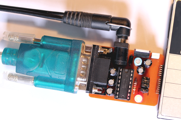
Connecting the calculator to your computer
Despite the additional uses for this board, the main thing you will probably want to do with this circuit is connecting your calculator to your computer. I could just connect a standard USB-TTL adapter to the top row of JP2 as explained before, but I’ll be going full-retro with a RS232 configuration, using almost everything this board has to offer:
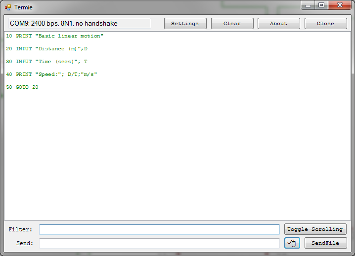
On my computer I’m using Termie, an open source clone of Termite (my simple terminal of choice), mainly because unlike the “original”, Termie can load files and send them to the target device.
To transfer a program stored in the calculator to your computer you need to go into programming mode (MODE + 1 in the FX880P), select the program slot you want to work with (in my case I’ll be using P1, so I press SHIFT +1) and write the following:
SAVE "COM0:5, N, 8, 1"
This will send the file through the RS232 connection at 2400 bps, with no parity, 8 data bits, and 1 stop bit. Make sure you have the same settings in your terminal software. When you are ready press ENTER on the calculator and the program should be sent to your terminal (from which you can save it to file or copy/paste it somewhere else).
To transfer a program from your computer to your calculator, go to programming mode, select the program you want to overwrite, and write:
LOAD "COM0:5, N, 8, 1"
In Termie now click Send File and select a text file containing the code. Make sure that the last line of your file also has a line break at the end, because that’s what the calculator uses to mark the “end” of a line. You could optionally start writing the code yourself in the terminal (making sure you send a line break after each line of code). When you are done sending the code press BRK on the calculator. The program should be stored in your Casio now.
You can change the communication speed but I’ve found that 2400 works pretty well. In the User Manual of the FX850/880P you can find the other speeds available for the LOAD and SAVE commands.
In the same text you’ll also find that you can actually create programs that open the serial port and talk to your computer or other peripherals, so in theory with this adapter you could make the calculator interact with pretty much any serial device including Arduino boards, sensors, modems, other microcontrollers, etc, etc.
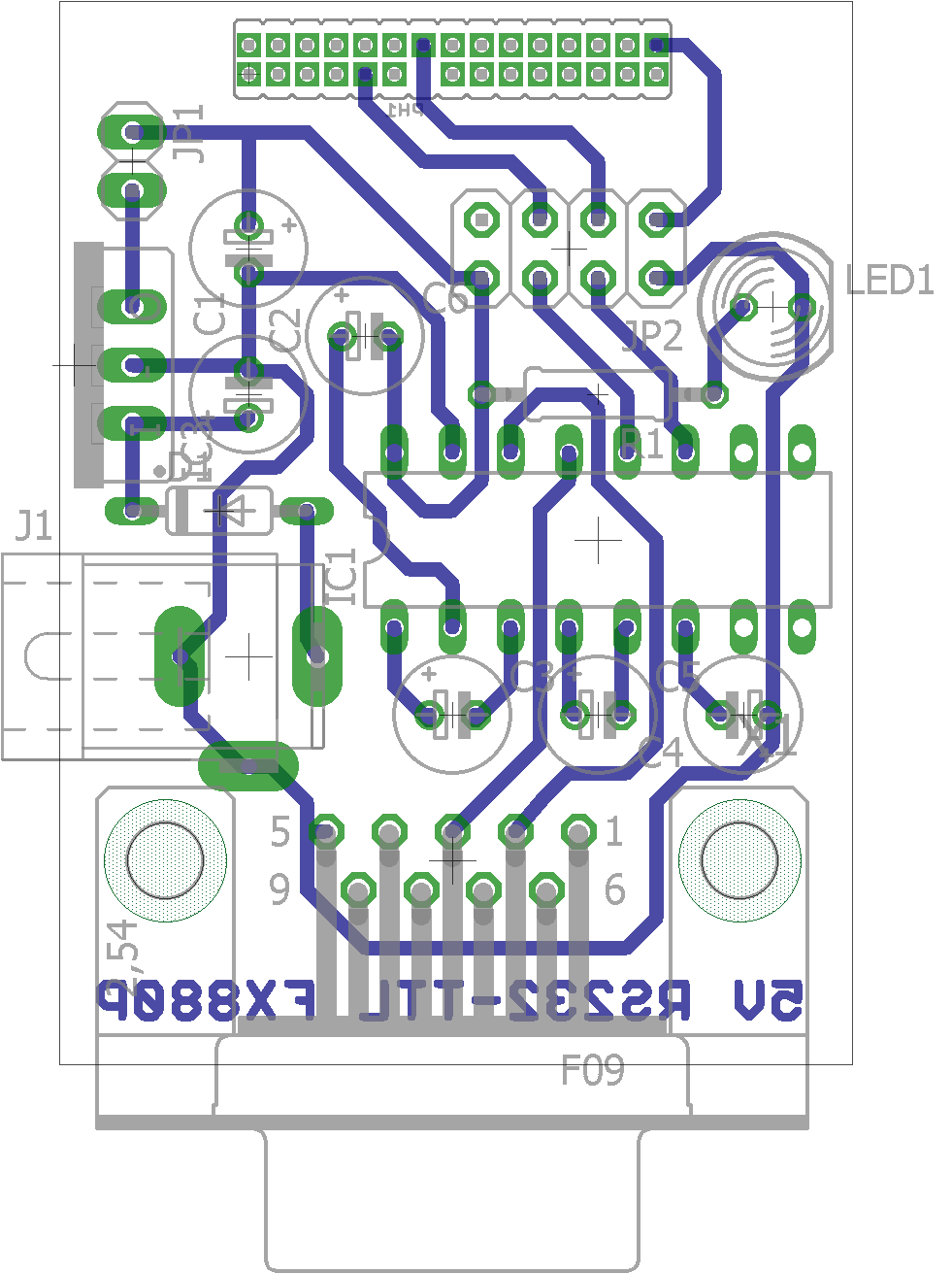
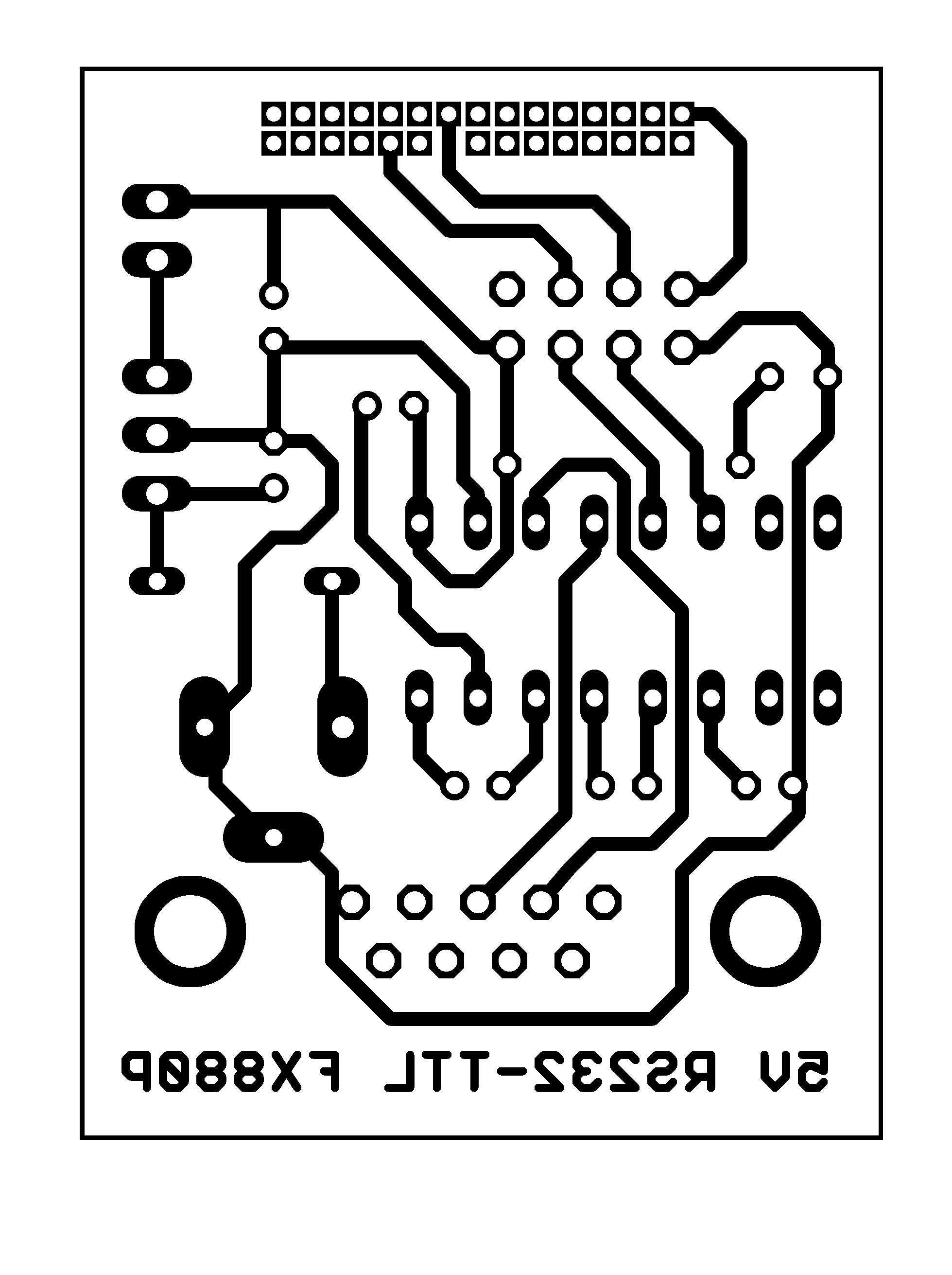
I’ll try to create a git repo with my circuits and stuff in Eagle format, but I haven’t gotten around to it yet. For the time being refer to the pictures below, they should be all you need to build this adapter.
Schematic and other pics


Hi,
I thought you might be able to help. I’ve left my FX850P idle for a very long time. Recently I just replaced 2x batteries.
The Calc mode works fine. But when I switched it to BASIC mode all asterisks and 0B, i.e. all contain programs and no memory left. I tried LIST and got PR error. I’ve tried hardware reset with the P-button and also removed all 3x batteries, no success. If the device is password protected I can’t remember the password. What can I do?
Have you tried with the ALL RESET button on the front of the calculator?
Actually, I tried that hole at the front first and no success. Then I found the P-button (hardware reset). I’ve also tried removing my memory extension (few times). Now it’s showing ~31KB. But all programs are still marked as used 🙁
I’d call that progress. Try going into programming mode and running “NEW ALL”.
NEW ALL caused FC error. Then I tried reset from the front again. That fixed the problem.
But I thought the P-button reset is “harder” than the front. I tried the back so many times.
Just for record, I guess it was the oxidation at the memory expansion which froze my programing mode. For some reason P-button reset didn’t help after fixing memory.
Anyway, thanks for your help. I’m going to test my “Transfile PC850” cable which has costed me ~100DM. I’m sure you will hear from me again very soo 🙂
I’m really happy to hear that your calculator is alive again.
I’ve had similar experiences with old units, in which one reset is oddly not enough, and I end up trying a combination of both until one of them makes it.
Anyway, I love these machines and it would have been sad to hear of one dying, so I’m glad yours is working again.
I’ve posted another question which didn’t appear, probably due to a link to a photo which requires approval. Did you get it?
I’ve replied to all the comments that were pending approval. If it was classified as spam by my blog then it’s long lost, I’m truly sorry.
What was your question?
This was my lost post:
I think I’ve too many unknown parts. I bought my connector in the 80s with a DOS program and it has worked. I lost the instruction.
1) Unsure with the pins. I assume the lower numbers are on the top row on the device.
2) Unsure with my large to small serial converter. I found it somewhere in my old stuff.
3) Nothing appears in port configuration of Termie. Doesn’t seem my USB cable is detected on Windows 10.
Do you have some suggestions how I can eliminate some of the unknowns?
This is a link to the photo of my connectors:
tiny Dot cc Slash tf850
Thanks in advance
Unfortunately I cannot see the picture. The link expands fine into google content, but then I see a “unauthorized” generated image.
Anyway, you can use a multimeter to locate the +5 and GND pins, assuming that it’s at least receiving power. That can help you figure out the orientation of the connector. If it’s not being detected by Windows it should at least appear as an unknown device in the “Device Manager”, if that’s not the case then it’s probably broken.
Sorry about the photo. It’s fixed now (tiny Dot cc Slash tf850).
I’ve installed a Windows10 driver. Now I can see “COM5 2400 bps, 8N1, no handshake” in Termie after setting the speed to 2400bps. I tried the command as shown: SAVE “COM0:5, N, 8, 1”
I got “Bad file name”. When I tried the command without spaces then no errors, but nothing happens. Do I have to do something on Termie?
Sorry for replying a week late. I still can’t see the picture, unfortunately. Same authorization issue.
At any rate, “Bad File Name” implies that the calculator didn’t like the file descriptor, and I think you are correct: there shouldn’t be any space between the parameters. If after running that you saw nothing on Termie, then your program was either empty, or you have a different problems (like wrong connector orientation). Another possibility is that your cable is using a microcontroller at a fixed speed (instead of a TTL-RS232 converter), and 2400 is not the speed it expects. I don’t think I can be of much help debugging issues of a cable that I don’t know much about, sorry.
Thanks so much for your time. I’ve fixed the link again. Hope it will work this time.
I’ll try other speed. I’ve also tried other orientation of the connector. It crashed after entering the command.
Basically, I don’t need to press any button on Termie to receive file, right?
Now I can see the pic, thanks. You don’t need to press anything to receive the file, as long as Termie and the port are opened (if it doesn’t say “connection closed” in the small box you should be fine). Considering you had to put an adapter in between maybe the TX/RX signals need to be reversed (with a “null-modem” cable).
I can’t find any description about those parameters in my handbook: SAVE “COM0:5,N,8,1”
If I change the speed what do I have to change?
Do you have any documentation for that?
I’ve checked the wiring of my converter. They seems to be correct.
For the details regarding the COM parameters check the FX-850/880 Manual. Page 84.
Hope that helps!
Hi Mr.E, I have just posted a reply to the previous responded before I replied to your very commendable construction. Very, very tactless of me but it’s now water under the bridge and all I can do is offer an apology! I hope you did not take too much of an offence?
I was wandering if you were prepared to fabricate a cable to enable me to connect my FX850 to my PC from the “not really DIY friendly” to a USB port on my PC. For a price, I hasten to say! Simply because, frankly, I wouldn’t know where to start to make the assembly of cables that you described in this web page. My email address is soda@talktalk.net. Thank you
Hi Stelios,
To be honest your other response did not even appear in my inbox. It went straight to “Spam” and I didn’t notice its existence until you pointed out that you had written a “rude” response before.
Now, your reply to Edward wasn’t rude at all, in my opinion, so I’ve left it intact.
It’s entirely possible to modify this design and make it USB-compatible instead, but I currently don’t sell ready-to-use versions of any of the projects on this page. I just make them for myself, mostly for fun or for educational purposes, and share the schematics and diagrams with all of you.
If you search ebay you will find several USB cables for the FX series of calculators. They are ridiculously expensive, but they will save you the trouble of making them yourself.
I ddo have fx880p and i want to put navigational program, is the connector still available? where can i buy it? and how much?
Hi,
As mentioned in the post, the connector itself is proprietary but the pin spacing is standard, so you can use a simple 1.27 double row right angle header, like this one. Those headers come in really long “strips”, so you’ll need to separate a 15 pins wide segment, so it’s 30 pins total.
Hi Edward, I found this thread just a couple of days ago, stupidly I used to have an FA-6 adaptor which was thrown away (yes! THROWN AWAY) by some ignorant person when I moved house a few years ago. I now find I need to connect my FX 850P to my PC and have no means of doing so. Did you manage to put together the connecting assembly of bits and pieces as Mr.E describes? I am not an electronics buff, I hasten to say, just an able wireman, so I’ve found Mr.E’s very commendable construction way beyond me. Interestingly, I too have my FX850 loaded with navigation programs (astronavigation by calculator many years back in Practical Boat Owner being one of them). If you feel like making direct contact with me my email address is soda@talktalk.net