 by
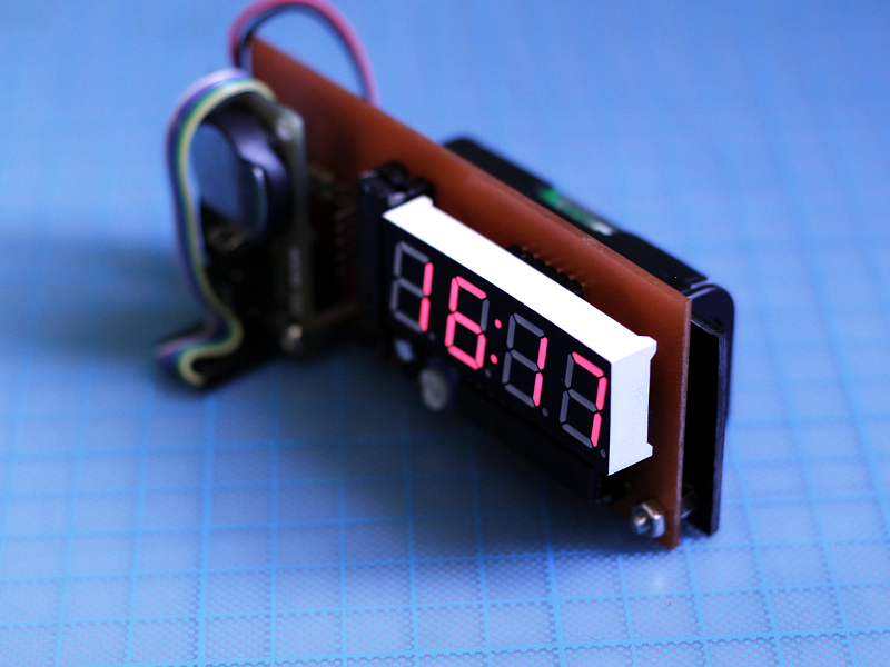
by I used to have a small desk clock that I purchased for a trip. It was cheap but it had some really nice features that I quite liked. It had large digits that I could see from my bed each morning, and it was also able to measure and display the current room temperature, which I always thought was incredibly cool for a clock.
The problem is, that it required a lot of batteries to work; 4XAAA for the fancy LCD backlight and soothing RGB glowing action, and 2xLR66 (button cells) for keeping the thing ticking and actually displaying time and temperature on its LCD screen. It worked reasonably well, but it was running through the batteries way too fast, in my opinion.
I didn’t really care about the AAA batteries dying in a month, because I could always use rechargeable batteries there, but the small LR66 batteries were killing me. Replacing them each 5-6 months or less wasn’t really a pleasure, especially since it meant setting time, date and alarms all over again, every time.
So I adventured in the journey of building my own clock. My main objective was to keep the number of batteries low, while also having the nice features of my previous clock, like the big numbers and the temperature readings.
Design
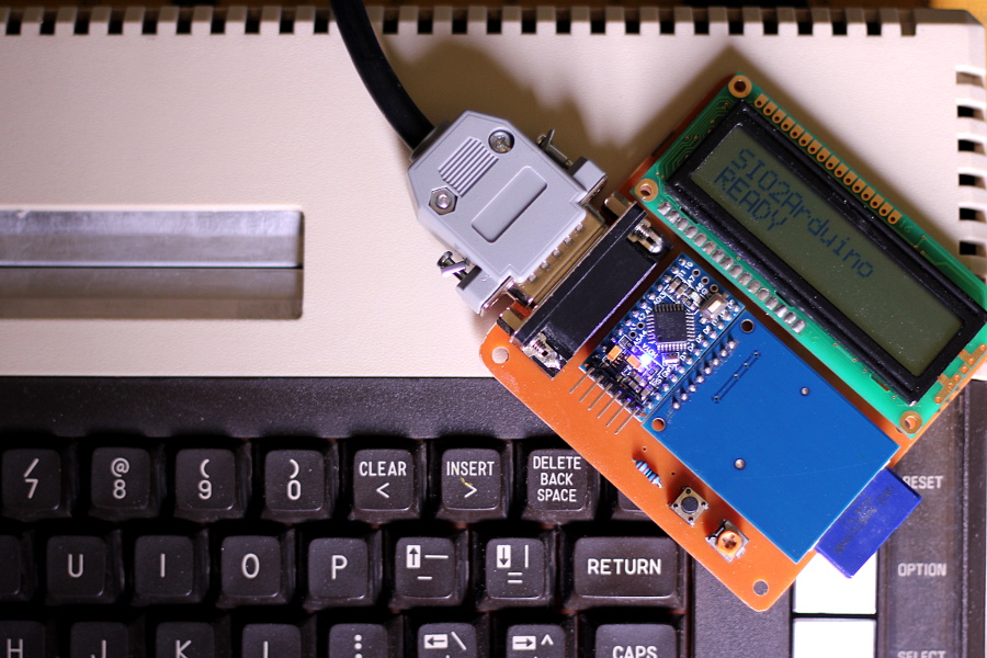
I already had a DS1302 RTC “time-keeping” module ready to be used as the base of this project. It’s a nice little board that can keep track of time and can retain this information even when no external power is applied. This is achieved thanks to its own backup battery -a pretty standard and easy to get CR2032- and it means that I can remove and replace the batteries of the clock without having to set the time again.
I believe this is the first project where I had to be super conscious about the power consumption of pretty much everything, and this led me to discovered that my PIC of choice for simple projects (Microchip’s 16F628A) was able to run at ultra low speed (48Khz) for continuous operation without drawing much current. It also has a sleep mode that draws even less current, and would be especially useful if you set this clock to wake up on an external interrupt, display time and then go to “sleep” again.
The other devices (the DS1302 module and the TMP75 temperature sensor) also had low-power features and modes, but required very little current and voltage to begin with, so I’m not currently using them.
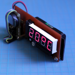
It was obvious that the most power-hungry component in the whole device was going to be the display, because LEDs are normally driven using a considerable amount of current (~10-20mA per segment, per digit).
Using a MAX7219 IC took care of the issue. This LED driver only shows one digit of the display at a time, alternating between them at such a fast speed, that it seems like they are all lit at once. Additionally it offers a software-controlled “brightness adjustment” -achieved by “pulsing” the active digit at certain frequency- that gives a dimmer or a brighter display at command. Obviously when the LEDs are not constantly “on” but are being “pulsed” instead, they consume even less power, especially if you don’t set your clock too be incredibly bright (a thing to consider if you have the clock near you at night, while you sleep).
I set the update frequency reasonably low, and further reduced the power consumption by using a big current-limiting resistor on the MAX7219, which of course meant that even at full brightness the whole thing was going to be not really that bright, and not really that power-hungry (NOTE: This was perfect for my poorly lit room, but might not be a usable configuration for a more well-lit environment, so feel free to play with the value of the current-limiting resistor and potentiometer if you build your own).
With this, the device was consuming around 4-5 mA at full brightness, and 1-2mA at lower settings (This value is not constant, as it depends on the number of digits that need to be lit at a given time and the number of segments that need to be “ON” to display the digits, which of course depends on the current time, date and temperature).
Given the voltage range of the components I can run this clock from 2x AA batteries, and assuming a power consumption of ~2mA, with a decent pair of >2000mAH rechargeable batteries the clock should run just fine for around 40 days, at which point -and assuming that the CR2032 is not running low as well- I should be able to replace the batteries without losing the current time nor date. This is also already more than what I was getting from my previous clock.
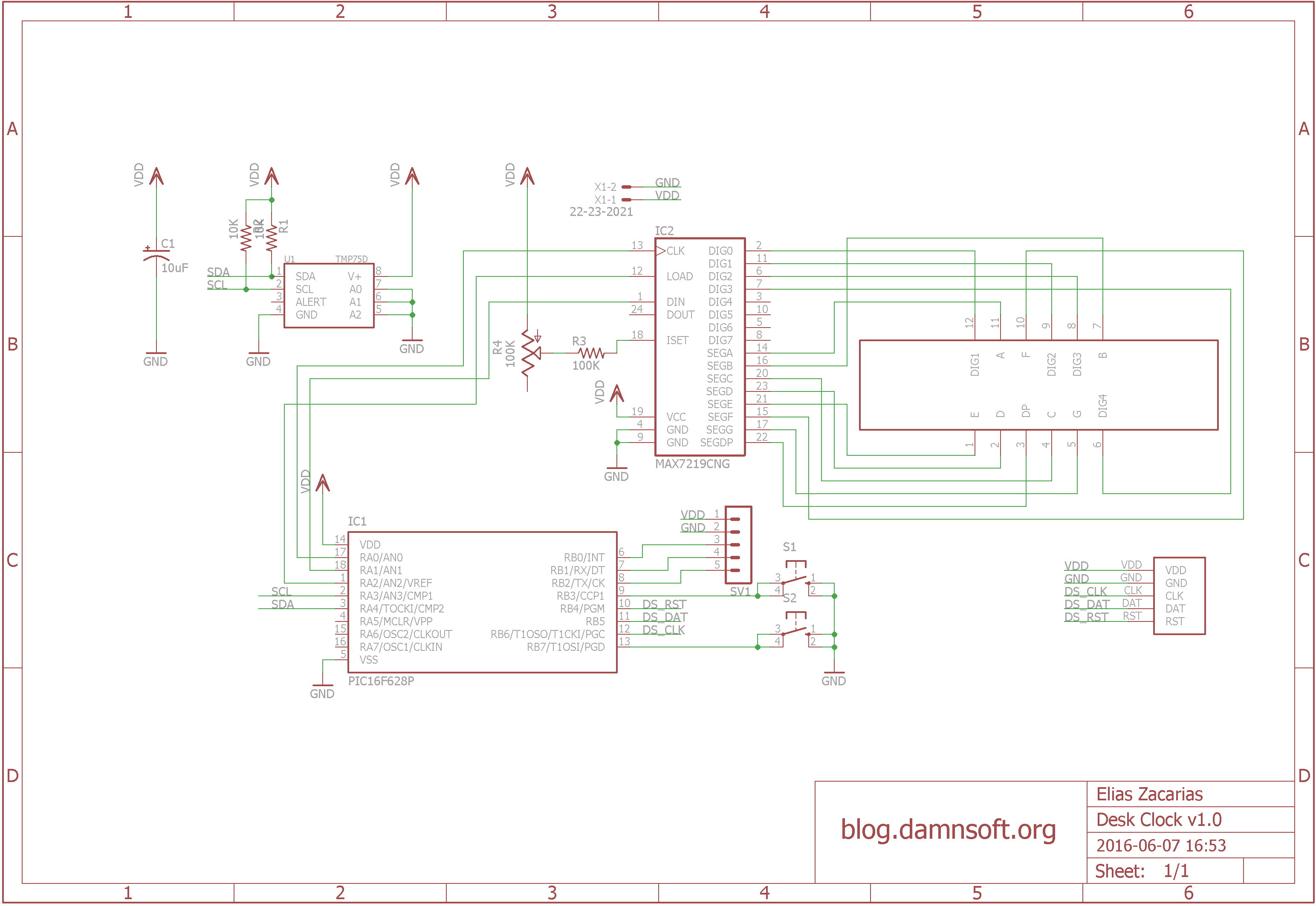
The board layout
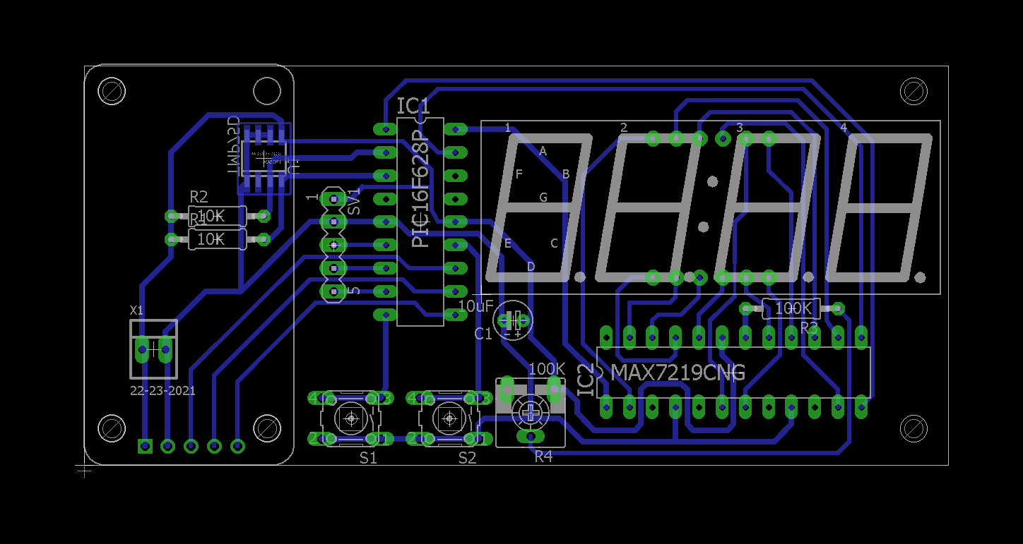
I designed the board in Eagle, and required some CAD models that are not part of the standard library.
For the 4 digits 7-Segment display, I downloaded and modified an Eagle file from OHM’S DOG blog, which saved me a lot of work as it only required minor modifications, and for the TMP75 I got a part from TI’s E2E forums.
I had to create my own model for the DS1302 module, but the rest of the components were either already in the Eagle library or were part of bigger known libraries like Sparkfun’s or Adafruit’s, which I normally keep in my Eagle lib folder all the time.
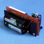
Speaking of the DS1302 module; I made the mistake of assuming that I could reverse the 5 pin connector of the board, so it would face the other side and snap right onto my PCB, but then I noticed that the board is single sided, so it was impossible. I could have made it so the module connected “face down” to my board, but it would have blocked the access to the CR2032 battery and made the PCB tracing a bit of a problem, so in the end I settled with a kinda ridiculous ribbon cable that goes over the module and connects to a right angle header between the boards. It looks nice, if you ask me, but now the clock is unnecessary thick and has a bit of a sci-fi cosplay prop vibe, which I’m not sure is something everyone will appreciate.
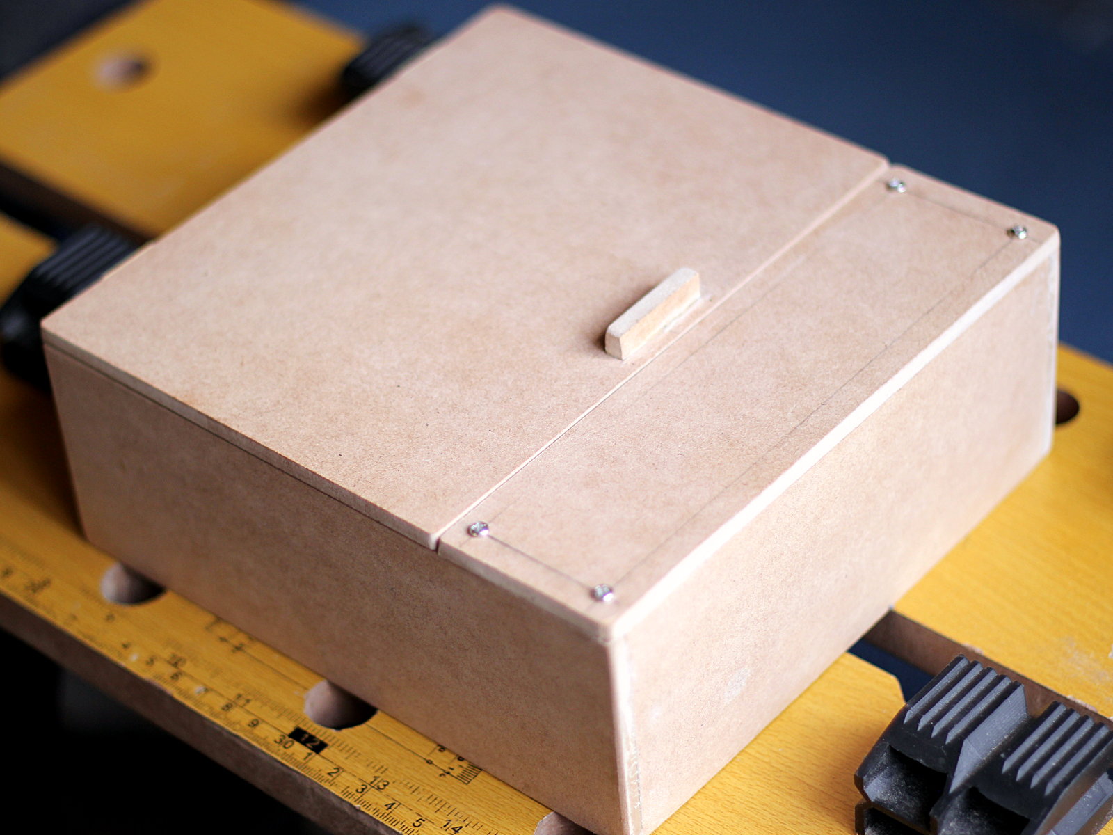
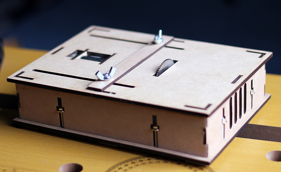
An advantage of having the module connect via a cable to the board is that I can later design a case, where the RTC module could perfectly be mounted somewhere else inside the box to make it less thick. Even in the current form I guess I could install the module in the acrylic backplate, right next to the AA batteries, but it would leave a horribly empty spot on the front side of the board, which -without a case- won’t look so good.
The firmware
I wrote the whole firmware in assembly for no good reason besides good ol’ fun, and I abused the macro system of the Microchip assembler to the point I feel a little bit guilty about it, I guess I took this approach because it gives me the benefits of in-lining code without the overhead of higher level languages or manually repeating the instructions myself. It even allows me to get syntactically close to procedure calls, by encapsulating the loading/saving of registers in parameterized macros.
The code uses 26 bytes of RAM (11.61%) and it’s 971 instructions long (47.41% of the program space) so there’s a lot of room for extra features. In fact the code could use even less if some macros (especially those that take no parameters) were converted to subroutines and some variables re-used even more than they currently are, but I don’t think it would really be a good idea. Converting macros to subroutines could potentially overflow the call stack in some instances if you are not careful, as the stack is only 8 levels deep and there’s a lot of code that relies on simpler subroutines that in turn call other subroutines, especially in the different software implementations of the communication protocols used by the modules.
Further reusing variables would make some sections unnecessarily confusing as you’ll need to use even more generic names for them, and would require careful analysis of the call tree so you don’t step over variables that are used by a deeply hidden subroutine that you happen to invoke at a certain point, and I’m not sure it’s worth the trouble just to possibly save a couple of extra bytes in a code that is already leaving like 90% of the memory available for other functions.
Having said that, I’m uploading the code to a git repo as well, so you are free to make changes, optimize or rewrite the whole thing if you like. I’d love to see what other people do with this project or if someone builds their own.
Failed attempts and Further changes
In an attempt to save more power, I thought that I didn’t need the clock to be constantly displaying time. I could make the clock clap-activated, so it would remain sleeping when not used, and would wake up with a clap (or a loud noise). Once triggered, it would display time, date and temperature for a couple of seconds, before going back to hibernation again. Following this blog post I was able to create such a clap sensor and while it worked, I soon discovered that it was not going to be possible to use it in my project.
The sensibility of this setup was incredibly voltage-dependent. At 5V the sensor reacted to my claps almost perfectly from almost anywhere inside my room, but as soon as the voltage dropped to 3 or less volts, I had to pretty much clap over the microphone for the thing to “hear” me. I tried using a DC-DC voltage booster that would ensure that the whole circuit would always receive 5V, but unsurprisingly, this increased the power consumption a lot, because the voltage-booster needs to draw more current in order to bring the low input voltage to 5 nice volts. With the booster, the clock at its “sleeping” state was consuming around 4mA, completely defeating the whole purpose of the sleep mode, and when it was displaying time it would go up as high as 40mA. It gave the clock a nice and constant 5V to run from, which made the display brighter, but even when “idle” it was consuming more (or the same) than my previous solution.
I ended up ditching this solution, but I added a connector to the board that exposes the RB0-RB2 pins. This allows me to do interesting things later like communicating to other devices through the USART module (RB1/RB2 pins) or visiting again the idea of having an external signal activate the clock (the RB0 pin happens to be one of the external interrupt input sources).
Play with it
For previous hardware projects I’ve only posted the images of the schematic and board layouts, so while that’s basically all the information you need to build those circuits, you aren’t really able to easily modify the design to suit your needs (if you so desire).
I really wanted to start publishing the Eagle files but never really got around building a special repo for them….Until now.
This is the first hardware project that I truly release in completely open source form, both in schematic and code, so I can’t wait to see what comes of it. I also hope to do this more often in a future, or upload previous projects if someone is actually interested in them. You can find the Eagle files and source code in my brand new electronics git repository. Not sure if creating a single repo for a collection of small is a good idea, but I guess I’ll find out in the long run, as I start adding more projects to it.


Hello Mr. E!
Amazing project! I’m trying to open your schematics and board but I get an error opening them on Eagle saying
Error:
line 8, column 16: This is not an EAGLE file.
I’m so interested on the model for the ds1302.
Thank you so much!
Hi. Apparently github messes up the encoding of Eagle files when you download them individually. Try downloading the whole repo as a zip file instead of the individual files.
This is a bit of an inconvenience I did not know of when I set up all my electronics projects in the same repository.
I’ll probably split my designs into different repos, or will offer a standalone “zip” file for the board design and schematics of each project in a future. For the time being please try going to the repo root and download the repo as a zip file.