by
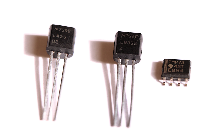
by I wanted to add a temperature sensor to a project I’m working on, and while I already had selected the perfect IC for the job, I decided to test a couple of other options I had, to see how they fare in comparison. I was originally going to compare only 3 sensors; the popular LM35, the not-so-popular LM335 and the kinda obscure TMP75, but as I started writing this post I remembered I got a Dallas DS18B20 as part of kit of sensors, so I added it to the mix to balance the digital-to-analog ratio of this comparison.
The Devices
LM35
By far the most popular sensor of the bunch. In fact, if you Google “temperature sensor” and click on “images” you’ll be treated to a bunch of pictures of this particular IC, and Google will actually suggest you to search for “LM35” instead. It’s THAT popular. It’s easy to see why, though; It’s inexpensive, theoretically accurate, and covers a wide temperature range (with a catch). Both this sensor and the LM335 are analog, meaning that they have a variable voltage output proportional to the sensed temperature.
LM335
LM35’s cousin-in-law; the LM335 comes from a family of LMx35 devices, comprised of models LM135, LM235 and LM335 (and their “A” variants, LM135A, LM235A, LM335A). The most significant difference between them is the temperature range; The 135 covers the widest range (matching the LM35) while the 335 covers the narrow-est. The “A” versions have the same temperature range as their non-A counterparts but feature increased accuracy. It’s worth noting than the “base” 135 and the 235 models have already a slightly better (advertised) accuracy than the 335.
This device is pretty interesting because there’s no min/max operating voltage range in the datasheet. Instead, you are instructed to wire a resistor R1 between the output and your +V source, carefully selected so it puts 0.5-5mA of current through the sensor. That’s apparently all it needs to operate and it couldn’t care less about the input voltage.
TMP75

Unlike the previous 2 sensors, this one is digital, meaning that it sends a series of pulses (serial data) with the numeric value representing temperature. You can configure the output resolution from 9 to 12 bits (which also affects the capture time) and set a couple of other functions like a one-shot mode, sensor shutdown, interrupt mode, etc.
Its temperature spectrum is not as wide as the LM35 but has a nice input voltage range that goes perfectly well with portable or battery-powered applications.
Since it’s incredibly small (and surface-mounted) I had to use a special clamp to connect it to the breadboard for testing.
Dallas DS18B20
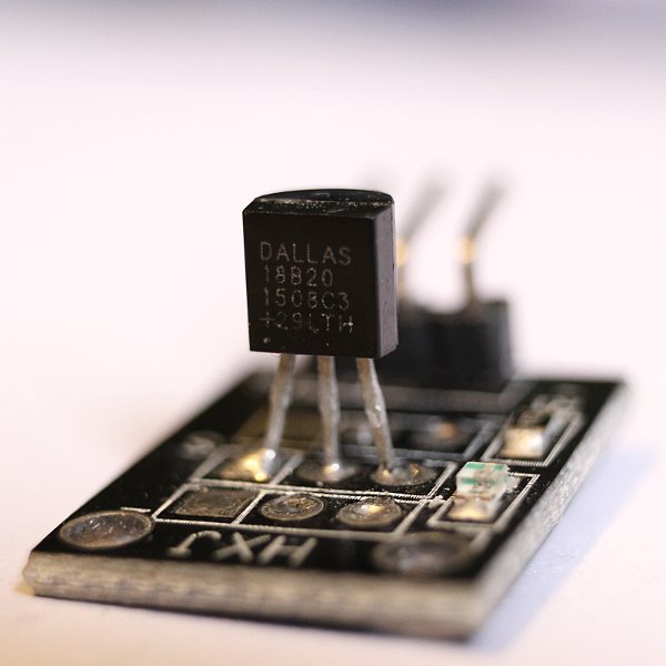
This is another digital sensor and it’s becoming increasingly popular.
It uses Dallas’ very own One-Wire interface, which I never really liked as it’s not the most straightforward protocol and can be a PITA to implement. Everything from device enumeration to reading and writing is done through 1 signal, alternating between sending and receiving, and including things like device address and CRC as part of the core protocol, which is kinda unusual.
This device can also be configured to obtain a resolution ranging from 9 to 12 bits.
You’ll find the basic specs for all of them summarized below:
| Sensor | Type | Output | T° Range | Accuracy | Supply |
| LM35 | Analog | Celsius | -55°C to 150°C | ±0.25°C (Room Temp) ±0.75°C (Full Range) |
4V to 30V |
| LM335 | Analog | Kelvin | -40°C to 100°C (LM135 covers -55°C to 150°C) |
1°C Typical (1-2°C Calibrated) (Un-calibrated could be as bad as 9°C!) |
0.5mA to 5mA (1mA typical) |
| TMP75 | Digital (I2C, SMBus, Two-wire) | Celsius | -40°C to 125°C | ±1°C Typical ±2°C Max |
2.7V to 5.5V |
| DS18B20 | Digital (One-Wire) | Celsius | -55°C to 125°C | ±0.5°C (From -10°C to +85°C) |
3V to 5.5V |
The first thing that you will probably notice is that for most room-temperature or weather monitoring applications, even the device with the most limited range is more than enough. For lab or industrial purposes there’s a chance none of them fits the bill.
Accuracy is normally within 1°C in ideal conditions even for the worst sensor. They behave “better” around normal room temperatures according to their datasheets and over their whole range their guaranteed accuracy drops, being the LM335 the worst offender, with a potential max error of 9°C if not properly calibrated! (more on this later).
Wiring and Technical details
Now that we know the ranges and overall specs of each device, let’s see how they operate and what is required to wire them to a circuit. For the purposes of testing them all I’ll be using an Arduino board, which has I2C/TWI (Two-Wire interface) support and analog input ports. Small (<1uF) capacitors will be added between the output of the two analog sensors and ground to stabilize their readings.
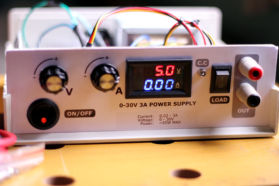
In order to get the most accurate analog values possible I’ll be using a stable lab power supply instead of the USB voltage, adjusting the source until I get exactly +5V for the whole circuit.
LM35
This device is incredibly straight-forward when it comes to its basic connection scheme. There’s a +V pin, GND, and output. When connected to +V and GND it delivers an analog voltage through its output pin linearly proportional to the current temperature, where each 10mV translate into 1°C.
It couldn’t possibly be any simpler, sure, but it has an immediately obvious drawback; the smaller temperature it can report when wired this way is 0°C (corresponding to a 0V output). For sub-zero readings this IC needs to be connected in “full-range mode”, which involves getting a negative-voltage power supply, making things really complicated all of a sudden. Whatever approach you want to use to “feed” this device the negative voltage it needs, will require additional circuitry, which makes it immediately less convenient to use unless the rest of your project already has a negative voltage line.
For the purposes of this test the LM35 sensor will be connected in its basic configuration. I won’t be testing below-zero cases.
LM335
The LM335 despite sounding like a rejected LM35 clone is actually quite a different beast. There’s a GND pin, an OUT/+ pin and an ADJ pin. You connect the output pin to a microcontroller and at the same time, it needs to be tied to the +V supply with a resistor whose value must be selected so a current of (typically) 1mA flows through the sensor to ground.
You can optionally connect a 10K potentiometer to the ADJ pin (tied between GND and output) for hardware fine-tuning and calibration, which should improve accuracy.
Once connected it behaves similarly to the LM35; 10mV equals 1 degree, but for this sensor they are Kelvin degrees, not Celsius. Both scales grow linearly at the same rate, the only difference being their “starting point”, with 0°K translating to -273.15° C. This means you only need to subtract that value from your readings to have the temperature in Celsius. Their choice of scale is actually pretty clever, because you not only get a Celsius-friendly reading, but you also get a reading that accounts for negative temperatures at the same time; A 0V output equals 0°K, which in turn means -273.15°C. No negative voltages are needed to measure temperatures below 0°C.
To test the performance in the most basic configuration possible this IC will be connected with no fine-adjusting circuitry (despite being incredibly simple to add).
TMP75
As mentioned earlier, this sensor is digital and the resolution is user-selectable. We will be using the highest resolution (12 bits) and will communicate to the device via the two-wire interface (TWI) protocol. No special modes will be used.
Once configured you only need to read from the device to get a 9-to-12-bits value representing the temperature.
At every possible resolution there’s a different output-to-temperature ratio, but it’s always a fraction with a power of 2 in the denominator, which makes things really simple, especially for ancient microcontrollers. In the 12 bits setting for instance, each “unit” in the output value equals 1/16th of a °C. For 11 bit results, it’s 1/8th of a degree, and so on. Binary shifting the result (or discarding the lower X bits) allows you to easily manipulate and compute the temperature, especially if you only need the integer part, requiring no floating point math or complicated code.
Also, you can connect up to 8 TMP75 sensors to the same 2-wire bus (by assigning each one a different address) thus saving a lot of pins in projects that require an array of sensors to be wired.
DS18B20
Connecting this sensor is also pretty straightforward, requiring only +V, GND and the infamous “one wire”, which needs a 4.7K pull-up resistor. In theory you can run the sensor without the +V signal in what’s called “parasitic” mode and obtain power from the signal line but I won’t be doing that.
Just like with the TMP75, the output value is constructed in a microcontroller-friendly way, with power-of-2 multipliers for fast and efficient math. It also shares the advantage of needing no extra signals if more sensors are wired to the bus.
For the code I’ll be using Miles Burton’s Dallas Temperature Sensor library and will have the sensor with the default settings (which I believe means 11-bit resolution, judging from the results). I tried setting the resolution to 12 bits and it was actually really slow to test as conversions took way longer (almost a full second) without noticeably improving the accuracy of the readings.
Test And Results
Here’s the full code that reads data from the 3 sensors and shows their output in the terminal:
#include <Wire.h>
#include <OneWire.h>
#include <DallasTemperature.h>

// CONFIG -------------------------
const int LM35_ANALOG_IN    = A0;
const int LM335_ANALOG_IN   = A1;
const int DS18B20_PIN       = 3;

const float ARDUINO_VCC     = 5.00;      // Should be 5V in any decent board unless directly powered from USB. measure with a volt-meter.
// TMP75 CONSTANTS ----------------
const byte TMP75_ADDR       = 0b1001000; // This is the address according to the docs when you connect A0-A2 to GND
const byte TMP75_CONFIG_REG = 0x01;
const byte TMP75_TEMP_REG   = 0x00;

OneWire oneWire(DS18B20_PIN);
DallasTemperature ds18b20(&oneWire);

void setup() {
 Serial.begin(9600);

 Wire.begin();
 ds18b20.begin();

 analogReference(DEFAULT);
 // TMP75 CONFIG ------------------------------------------------------
 Wire.beginTransmission(TMP75_ADDR); // Address the TMP75 sensor
 Wire.write(TMP75_CONFIG_REG);       // Select the configuration register
 Wire.write(0b01100000);             // Write desired config: No Shutdown mode, Termostat in Comp. mode, Def. Polarity, Fault queue 1, 12 bit resolution, One-Shot disabled
 Wire.endTransmission();

 Wire.beginTransmission(TMP75_ADDR); // Address the TMP75 sensor
 Wire.write(TMP75_TEMP_REG);         // Select the temperature register, so further read requests will retrieve from it.
 Wire.endTransmission();
}

float read_tm75(){
 Wire.requestFrom(TMP75_ADDR, 2);
 int tm75_reg = (byte)Wire.read()<<8;
 tm75_reg |= (byte)Wire.read();
 tm75_reg >>= 4;
 // In 12-bit mode, resolution is 0.0625°C (1/16th)
 return tm75_reg/16.0;
}

// Returns the Analog input in "mV"
float analog_input_mV(const int analogPort){
 return ARDUINO_VCC*analogRead(analogPort)/1.024;
}

float read_lm35(){
 return analog_input_mV(LM35_ANALOG_IN)/10.0; // 10 mV per °C.
}

float read_lmx35(){
 return analog_input_mV(LM335_ANALOG_IN)/10.0 - 273.15; // 10 mV per °K
}

void loop() {
 Serial.print("LM35: ");
 Serial.print(read_lm35(), DEC);
 Serial.println(" C");

 Serial.print("TM75: ");
 Serial.print(read_tm75(), DEC);
 Serial.println(" C");

 ds18b20.requestTemperatures();
 Serial.print("DS18B20: ");
 Serial.print(ds18b20.getTempCByIndex(0), DEC);
 Serial.println(" C");

 Serial.print("LMx35: ");
 Serial.print(read_lmx35(), DEC);
 Serial.println(" C");
 Serial.println("");

 delay (1000);
}
And this is the result:
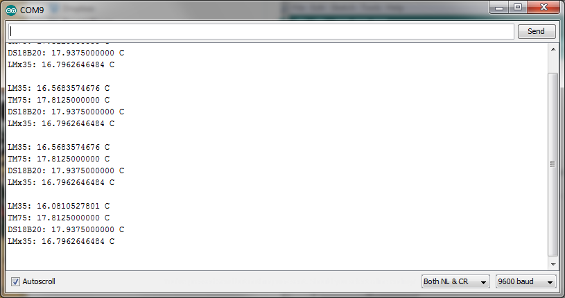
In my tests, the 4 sensors give quite similar readings no more than 2-3°C apart. I only had an ancient mercury thermometer to compare, but the LM35 seemed to be the most accurate of the bunch, with an output consistently closest to the “mercury” readings. The TM75 came at a very close second, always well within the ~1°C accuracy range.
Can’t be seen in the picture but the LM335 had the most variable performance of the bunch; sometimes it was spot-on and sometimes it missed by ~2°C compared to the others. Connecting the optional adjust potentiometer and calibrating the device at ~25°C certainly helped a bit, but accuracy would always drop more and more as you move further from the calibration point. This comes as no surprise however, as the datasheet was very clear about this. I never saw the awful worst-case of a ~°9C difference though; with or without calibration it was never worse than ±2°C, even when I applied localized heat to the whole setup, rising temperature to around 80°C (where I could no longer use my mercury thermometer to compare).
It’s worth noting that a problem common to both analog sensors is that they require a very stable voltage supply that should remain at a constant (and known) value at all times for accurate readings, which may be a problem in battery-powered applications. You’ll also need to select your components carefully so no significant voltage variations are introduced due to temperature changes.
Overall the digital sensors had the most consistent behavior, with the TMP75 triumphing the DS18B20 with a faster response, and better protocol options. Both had a generally stable output, with the numbers varying just slightly between consecutive reads. I didn’t see a “superior” accuracy in the DS18B20 despite the datasheet stating otherwise. I think both were able to keep an accuracy of ~1°C (compared to the mercury thermometer) at all times, and if anything the TMP75 had what seemed to be the closest readings.
Conclusion
If you need accuracy and can provide the sensor with everything it needs for stable and full-range readings, go with the LM35. At least it seems to me that this is a component better suited for robust designs that can afford having a really stable power supply with a perfectly balanced negative line.
If you definitely need to go analog and accuracy isn’t really a concern (or you can get your hands in the more accurate versions of the sensor) go with the LM335 (or any sensor from the LMx35 family). The fact you can get below-zero readings with no extra circuitry is really nice, and having the option to tweak and improve its accuracy is also pretty useful.
Analog devices will always have a place, especially when your design doesn’t include a microcontroller or any form of programmable processing unit. For most cases however (where I assume a MCU is present) I’d recommend getting a digital sensor, with the TMP75 being my first recommendation due to performance and versatility. The Dallas DS18B20 isn’t bad either, it’s just tied to a complicated protocol with very slow response times, which -depending on your application- could be a deal-breaker.
NOTE: Since I did not have a precision instrument to compare with, I advise you to take my observations regarding accuracy with a grain of salt. Results in terms of consistency, ease of use, features and response speed are what I hope you consider the most from this post. In fact, for both digital and analog devices, accuracy can always be improved if you are willing to perform additional math; you can compute the error margins at different temperatures across the whole supported range (comparing against a precision thermometer for instance) and then compute an “adjustment” function that can be applied to the output of the sensor.