 by
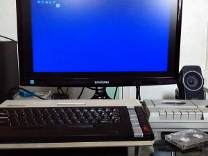
by A while ago -and after a couple of trips to our local “flea market”- I managed to get my hands on a fully working vintage Atari 800XL. It took some tests and soldering work, but I ended up with a fully working 800XL with a XC12 cassette deck (I even got a defective cassette deck that it’s mostly working now after some repairs). I also built a video cable to have the “vastly superior” RCA video output instead of the noisy “TV” RF signal.
The tape deck loads and saves to cassette perfectly, but every read/write operation takes ages. Not that I mind waiting, to be fair, but since there seems to be better alternatives (like the floppy disk drive) it makes no sense to just stick to this, especially since I intend to do some development on the device.
The Atari has a sort of “Universal” peripheral port to which many devices can be connected, called SIO (Serial Input/Output) and it’s pretty much the 80’s equivalent of the USB port. The cassette deck, diskette drive, and other hardware like printers, modems, etc), they all use the SIO interface.
I don’t think I’ll find a working floppy disk drive anytime soon, as the best I could get was the tape drive. Luckily there are several schematics online for hardware that “emulates” a disk drive with more modern storage options like SD cards, so I decided to try one out.
SIO2Arduino
The best solution I found was SIO2Arduino, by Daniel Noguerol (Wizzo Software). It uses widely available modules and offers different “configurations” that gives you flexibility over the features you want and the components you have at your disposal.
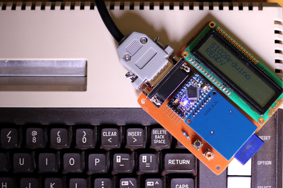
Since I actually had all the parts for it, i went with the more “complete” build that includes a LCD screen and a button to scroll through the list of available “disk images” inside the SD card.
I originally wanted to wire the modules together “as is”, but as I didn’t find a suitable “box” to mount the components inside, and because I also wanted a tight and “compact” unit, I ended up making a board for the whole thing.
Before we begin
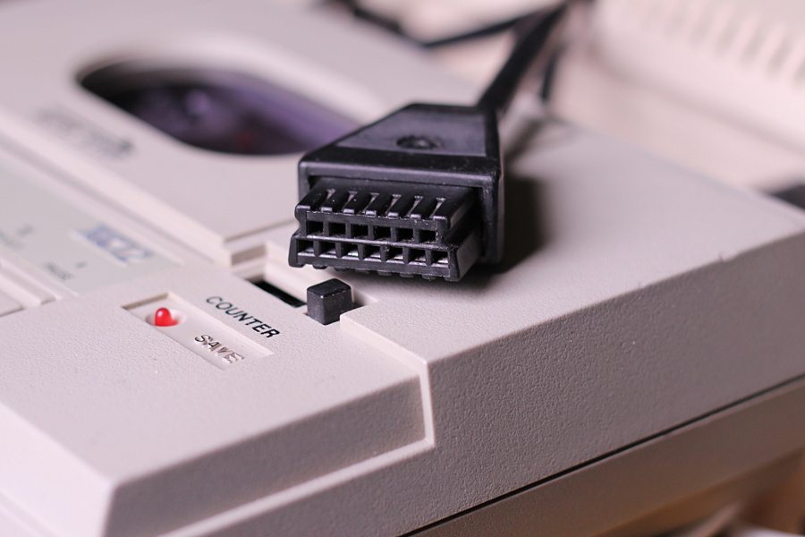
The first big problem you will face if you want to create hardware for the Atari is the SIO connector, which is a highly proprietary 13-pin beast with a weird pinout. As it has always been clear to me that I’d eventually want to make hardware for the Atari, or use the tape deck on my own custom microcontroller projects, I hacked the SIO cable the moment I got the Atari working. I cut the cable from the cassette drive somewhere in the middle, and carefully wired DB15 connectors on both ends matching the SIO pin numbers. DB15 is a more standard and widely available connector that’s still easy to find, so it’s a good choice for this job.
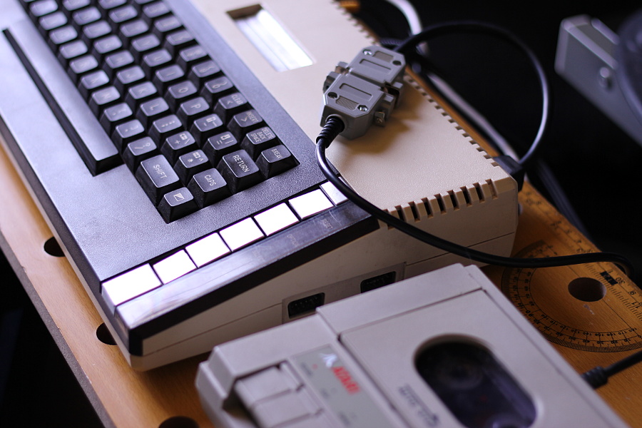
With this modification you get a XC12 tape deck that uses a DB15 connector, and a SIO-to-DB15 adapter that can be used to connect the Atari to the tape deck as before, or to other (custom-made) peripherals using a DB15 port. This is a mostly harmless hack; The Atari still has its SIO port intact to accept standard SIO peripherals, and the tape deck (with the adapter cable) can still be connected to this and other Atari computers.
SIO2Arduino Hardware
The components for my build are a SD Card module, an Arduino Pro Mini/Nano, an alphanumeric 16×2 LCD, a couple of resistors, a potentiometer and a push button. I wired them together following the pinout on Daniel’s site for the Arduino Uno (which is essentially the same as the mini, but in a bigger form factor and integrated USB-TTL converter). Please bear in mind that where he says to wire a button with a pull-up resistor, he actually meant pull-down.
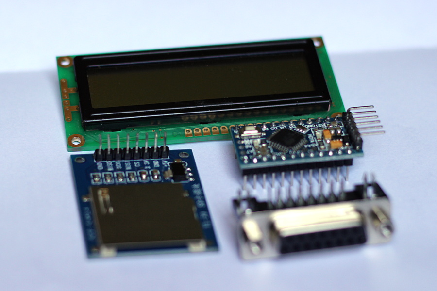
I decided to use a VERY old LCD I had that lacks backlight (I don’t think you can even get them without BL nowadays). I like to use old modules and components whenever possible, because the more time it passes, the less likely it is for them to be useful in a project.
PCB
The board I made is nothing to write home about. It just connects everything according to the instructions in the original site. There’s also the required 10K pot for LCD contrast control and a current-limiting resistor for the LCD backlight (in case I eventually replace the LCD I used with one that actually has BL). For the board layout I used Sparkfun’s Arduino Mini footprint from their Boards Library, and the HD44780 LCD model from this repository. I tweaked both parts to make the pads thinner and longer. This allows me to run wires between pins while also gaining soldering surface.
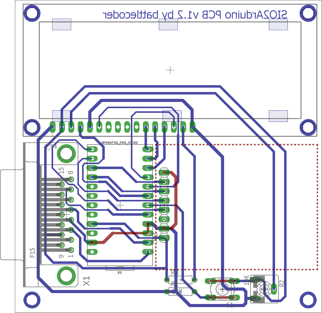
I had to make the PCB twice because the first time had problems with the etching. Several tracks had to be fixed with solder bridges and wires. The second board I made turned out WAY better, although I missed the opportunity to add a label with the device name and version. I’ve added that to the board files, so in further revisions I don’t forget to add it.
SIO2Arduino Software
The firmware wrote by Daniel is fairly straightforward and you can select the hardware and features you want by editing the config.h file following the instructions provided in his page. The code didn’t compile for me though. It failed due to several calls to methods that are declared later in the code. Adding the corresponding forward declarations fixed this. An older version of SdFat is required to compile the code, as as it seems to have issues with later releases.
I also wanted to have both the Reset/Automount feature and the image selection behavior so I modified the code to only check the “reset” button during startup and also improved the button handling so it doesn’t trigger continuously while you keep the button down. There’s actually a isSwitchPressed variable that it’s defined but never used, so I think the author at one pointed wanted to add that feature. Since it was already there, I used that very same variable to keep track of the button state.
I forked Daniel’s code and you can find my modified version on my personal git repo. With the changes you should be able to have both the automount and the image selection features if you so desire. The PCB I designed is also in my github repo.
SIO2Arduino works really well and now games load in seconds, not minutes. It’s also easier and less time-consuming to copy files into an SD card than it is to convert each file into a waveform and later record them in a tape. Massive improvement to be honest, so If you own an Atari I’d recommend you to build one as well.


O have this one installed in my Atari 800XL. It works perfectly.
I’m really happy to hear that!
Nice and clean work! Thanks!
I have SIO2Arduino inside my old Atari 800XL 😉
Thanks!
Having it inside the Atari is a pretty neat idea, especially considering there’s a lot of space inside the 800XL case to fit the electronics without a problem.