 by
by 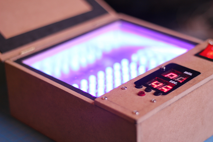
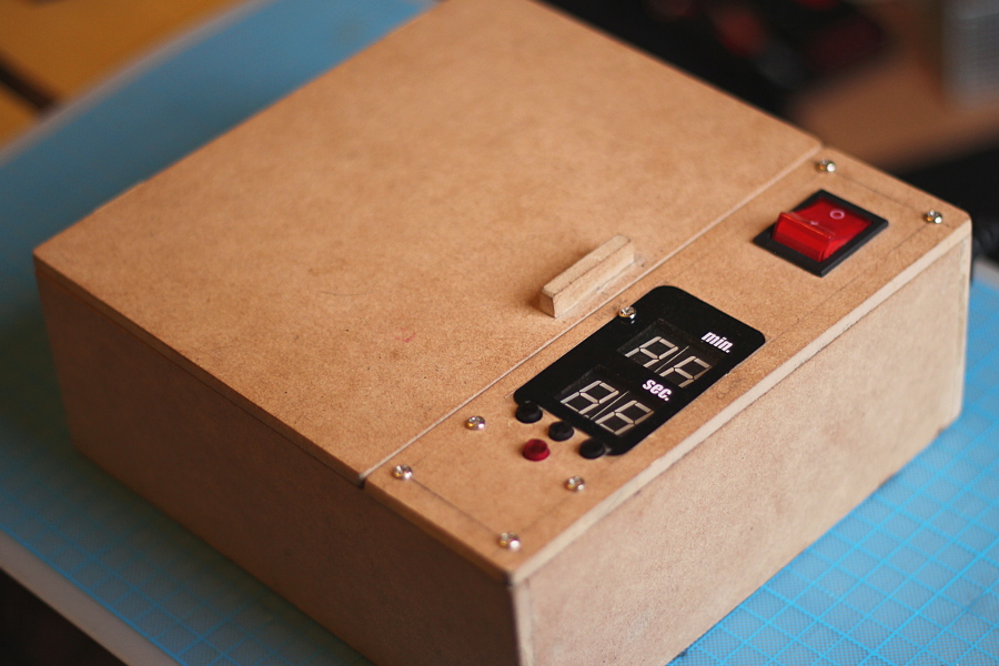
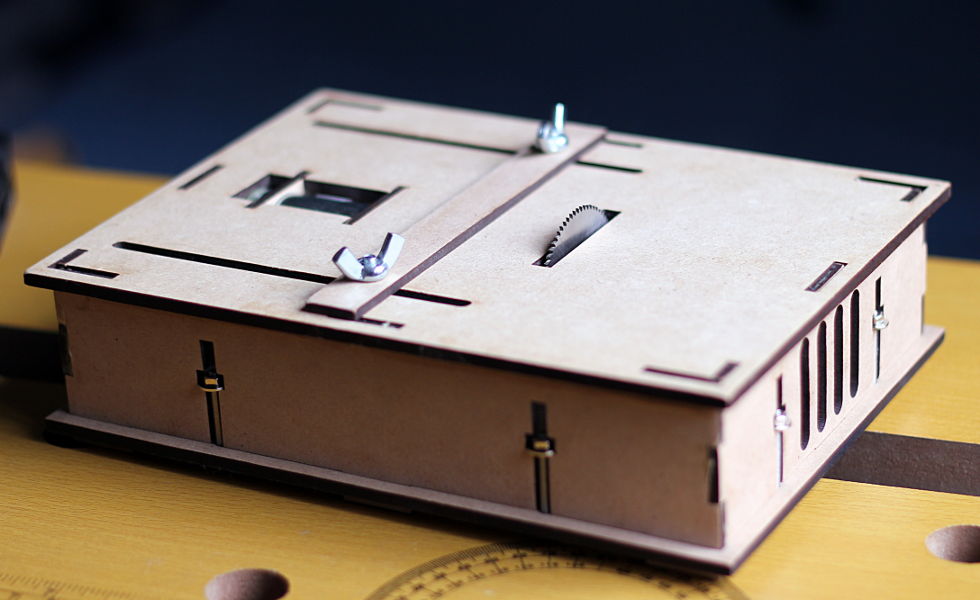
This is the second part of my adventure building a UV Exposure box, in which as you can see, I actually finished the build. In the first part I made the structure and planned the electronics. This part covers a whole lot more, distributed over many weeks doing small things here and there.
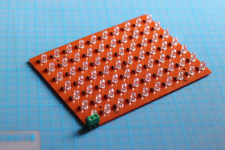
Building the electronics took me longer than I anticipated because I was waiting for a few parts to arrive, and also because it’s been hard to find the time to manufacture the actual boards. Of course the first board I did was the UV LED PCB, which I had already designed in KiCad by the time I wrote the first part, and was the biggest board in the project.
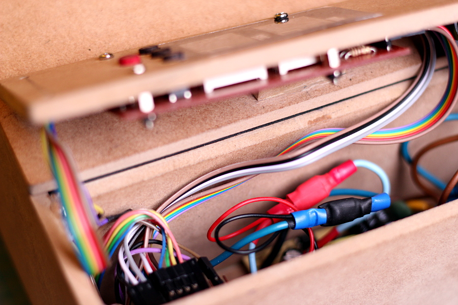
For the control circuitry I made two boards: One being the actual panel (buttons and display) and the other one being the logic and I/O control unit, which was basically a bare-minimum Arduino with a relay. The panel worked fine but I ended up ditching the second board entirely, as I discovered later that I made a mistake with the relay-driving circuitry, and instead of spending more time re-designing and etching a board again, I opted for using an Arduino Pro-mini, and a separate relay board that I made on a perfboard, connecting everything with female-to-female dupont cables.


Using a relay as the switching element is a bit of an overkill, I know, but since I’m a big fan of reusing electronics, or re-purposing stuff, I thought that it was a good idea to make this whole circuit a more general-use programmable timer that I could eventually use in other applications. I also like the “clicking” noise that relays make; It serves as a secondary indication of when the device starts or stops.
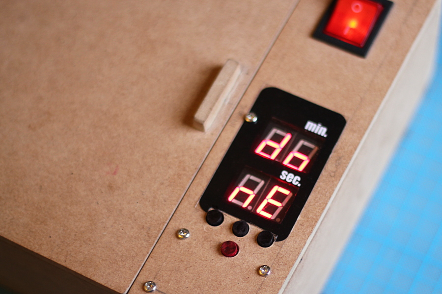
I also decided to use individual digits instead of a “proper” 4-digits 7-segment timer display (like the one I used with my clock), so I could split the counter in two lines. This was because I wanted the control panel to be at a side of the unit, vertically, allowing the AC socket connector to be in the back, which is always more convenient for bench-top devices. You will also notice that instead of driving the displays with a dedicated IC I’m doing all the digit-toggling work in the Arduino code, and I’m using individual resistors for current-limiting each segment.

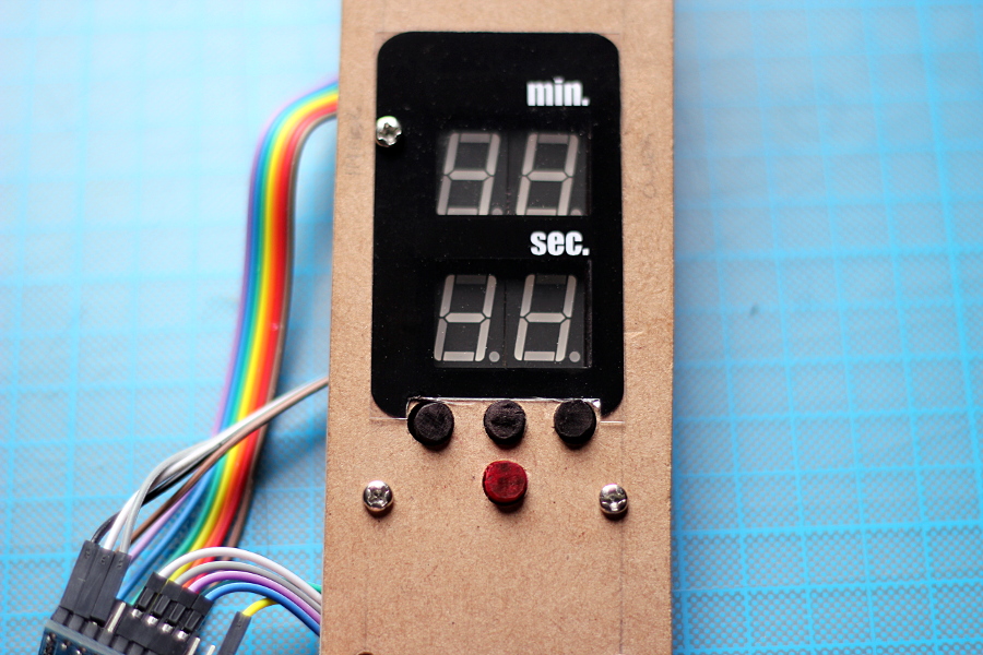
Please consider that when I designed the overlay mask for the display I did not have a layout made for the buttons nor the mounting holes, so you’ll not find them in the template. If you decide to follow my layout you may need to use an xacto knife and a drill to modify the already printed piece accordingly. Alternatively you can modify the SVG files to consider those elements.
The firmware, schematics and layout for the front panel and UV led boards are all in the repository. Starting with this project the PCB design and schematics are in KiCad format.
Whether the box works for what I wanted is yet to be seen, but chances are that it will, although I may need to run some tests to get the timing right for each process with my box.
The firmware currently works but I’m sure I can add some more user-friendly features like some visual indication when the unit is refusing to start because the lid is open, or storing in EEPROM several user-configurable presets that can later be used with ease.
Hardware-wise I think I only need nicer buttons. Sharpie-painted wood pegs don’t look particularly good so I may end up designing plastic ones as soon as I get myself a 3D-printer.
For the time being I leave you with a video of the safety feature in action. Unless you disable it, there’s no way you are going to see the UV lights if you open the box while it runs. Because you know; safety is number one priority.
My UV box working. A reed switch senses when the lid is open and automatically pauses / turns the UV LEDs off. #Electronics #safety #DIY pic.twitter.com/DyHKcK6IiY
— battlecoder (@battlecoder) June 26, 2017
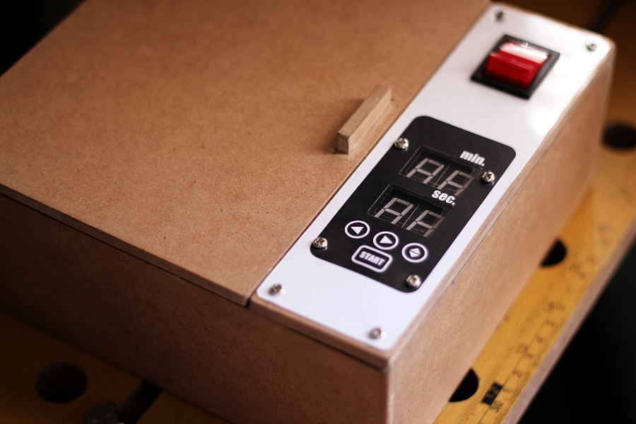
BONUS UPDATE!
I recently designed a proper front panel, and you will find it now in the git-hub repo.


Hello sir Elias zacarias introduce me Audrey from indonesia and interested in your project for school lessons on how to make UV Exposure Pcb box can you help me how to make Uv exposure as you made thanks
Hi Audrey,
The PCB files and schematics are all in the git repository. You will find there other files like the panel layout and arduino code as well. The only extra parts you will need are a 5V power supply, an Arduino mini or nano, and an enclosure, which you can make in many ways, not only in wood as I did in Part 1. The magnetic reed switch can be replaced by a standard switch, as long as it still allows your box to close perfectly. It’s important to avoid any leakage of UV light when the box is running.
If you don’t have the materials or knowledge to make the PCBs yourself, you can build the electronics in perf-board, following the schematics. That’s what I did in fact with the relay board, as you can see in the pictures.
If you build yourself one please let me know! I’d love to see your version of this project!