 by
by A couple of months ago I was asked if I could prepare a sort of workshop on one of my favorite topics: ASM Programming for PIC microcontrollers, which I of course accepted on the spot. Now, I wanted to include a couple of “hands-on” lab sessions in this workshop, and because of this, I needed a way for all attendants to actually work with real PICs that hopefully did not involve purchasing PIC-programming hardware in bulk for what is probably going to be a one-shot activity.
The Quest
Simple DIY programming circuits exists, and in fact, my first PIC programmer was a home-built “Enhanced” NOPPP (No-Parts PIC Programmer); a fully functional device that required only a couple of components (Not really “No-parts” but pretty close to it). The problem is that it used the PC parallel port (R.I.P), and required an external power supply. And this goes for pretty much every “classic” DIY PIC programming circuit; they all either require extra hardware or can no longer be used on current computers.
The main obstacle here is that PIC devices are normally programmed using HVP (High Voltage Programming), which involves using a voltage way above their regular operating level. This is part of the reasons they require additional hardware. In old designs this higher voltage was obtained normally from an external power supply or from highly-specific hacks that only worked on ports no longer available on PCs (*cough* RS232 *cough*). Modern designs use voltage-boosting circuitry, or still resort to external power.
But I know that several PICs support LVP (Low Voltage Programming) which means they can be programmed using only ~5V; greatly simplifying the required hardware. With this in mind I thought that it should be easy to make a cheap and “no-parts” (In the sense that requires no external components nor assembly) LVP PIC programmer using something like an Arduino.
Using Arduino also has many advantages; Compatible boards (especially “nano” and ” Pro mini” variants) are not only widely available, but also quite cheap, and more than capable of handling all the handshake and 5V logic needed to program a PIC, with no extra components required. They are also quite popular, so chances are that any person interested in this project already has one. They also connect to the computer via USB (well, a “comm” port managed by a USB-Serial chip, but still counts) so it should work for everyone with a computer manufactured after 1996.
More importantly, however, a bunch of Arduinos will still be useful to me after the workshop is over, and getting a dozen of them won’t be a problem.
Great, right?
Well, thing is…if you start looking for “Arduino PIC programmer” online, you’ll be greeted by a number of abandoned projects, solutions made for a family of PIC devices that are NOT compatible with the one I want to use, alternatives that require needless extra circuitry (like a custom Arduino shield or external power adapters … because HVP…duh), or slightly-related projects made for platforms so expensive that it doesn’t even make sense to even consider them an alternative for what I need (Yes, I’m talking about THAT one project that uses a RaspberryPi).
As none of the existent solutions worked for what I wanted, I decided to roll my own, focusing (at least initially) on the PIC I wanted to use for the workshop; The simple yet versatile PIC 16F628A.
Also, I thought this was a fun challenge to tackle and something I’d enjoy working on. I’ve done many tools for micro-controllers in the past, but this was my first dive into the hardware-specific side of the programming procedure.
The Result
Fast-forward through the couple of weekends several months working on this (sorry, other projects got in the way), I’ve managed to make a firmware for Arduino boards that can program a handful of LVP-ready PICs using nothing but the Arduino board and a CLI (Command Line Interface) utility that communicates with it. The CLI was written in Java for portability, so it should work on Windows, Linux, OSX, etc.
It can currently program the following devices:
- 16F87, 16F88
- 16F627A, 16F628A, 16F648A
- 16F873A, 16F874A, 16F876A, 16F877A.
- UPDATE: Support for 16F87X “non-A” devices has been added.
More PIC devices can be added later I guess, but I reckon it won’t be a simple task; different families of microcontrollers support different programming commands and algorithms, and I’ve only implemented those supported by the microcontrollers above.
You can find both the firmware and the command line interface on my GitHub repo.
Usage
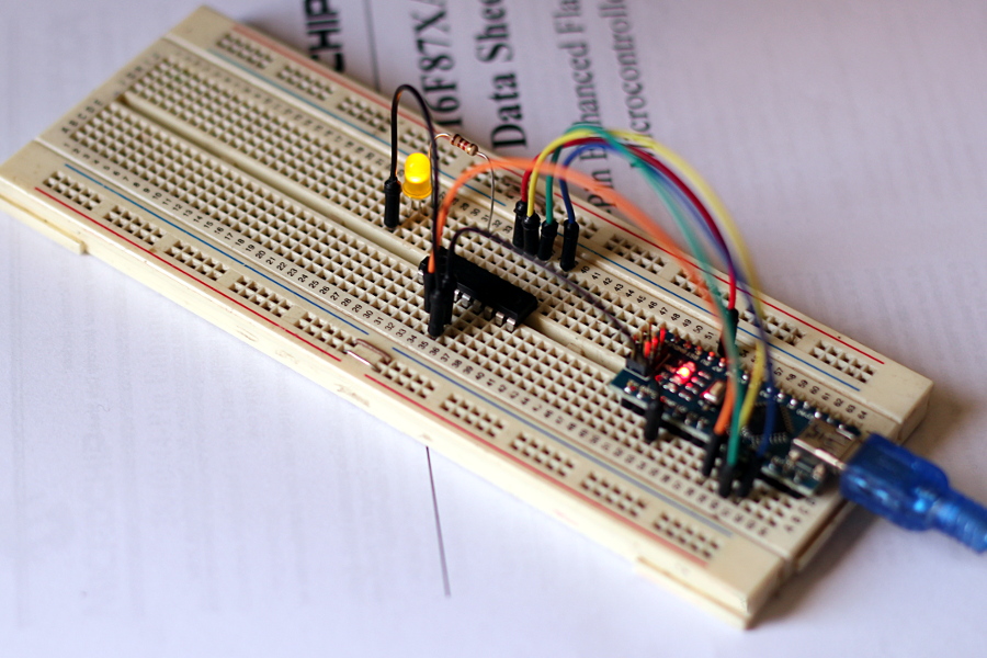
All the information to run this project can be found on the GitHub repo. And you can always run the command line utility without arguments to get a list of available parameters, but to further illustrate how truly “no external parts” this programmer is, this is how you would connect an Arduino Uno with ZEPPP to a 16F628A:
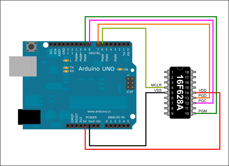
I’d say this is one of the “simplest” PIC programmers out there.


HI Good evening,
I am Benny from Kerala State of India.
I try to use your ZEPPP program from Github.
But, when I try to compile it gives me 3 errors :
zeppp.ino:29:1: error: ‘ZEPPP_RET’ does not name a type
zeppp.ino:30:1: error: ‘ZEPPPCommand’ does not name a type
zeppp.ino:31:1: error: ‘ZEPPP_RET’ does not name a type
Please help me to resolve it.
I know, I am not good in Programming.
Thank You
Hi, I would need to test, but maybe that’s a problem with more recent versions of Arduino. The one I have currently installed doesn’t give any errors (Arduino 1.8.13).
Can you try replacing
#define ZEPPP_RET charwith
typedef char ZEPPP_RET;Regards,
Hola mi nombre es Andrés Raúl Bruno Saravia soy de Bruenos Aires Argentina, soy profesor de electrónica y entrenador cerftificado por Microchip, su programador es excelente, lo arme para usar en mis cursos con mis alumnos, funciona muy bien, lo he probado con el PIC16F628A, sin embargo tengo problemas al programar los PIC16F883, cuando los comienza a programar lanza un error de un espacio de memoria que no esta implementado en el PIC, podrá decirme si usted ha encontrado ese problema? Yo he leido que justo esa familia de PIC el soporte no esta completo. Puede ser que sea por ello? Desde ya muchas gracias por su excelente proyecto lo felicito
Hola Andrés, muchas gracias por tus comentarios. Me da muchísimo gusto oír que mi programador ha resultado útil para sus cursos. Lo único que no está implementado en el 883 debería ser escribir/leer la configuración de calibración (que rara vez es necesaria) y la programación por bloques (que es más rápida, pero la programación secuencial funciona bien). Puede que haya puesto mal los límites de memoria del dispositivo por lo que me cuentas. Puedes decirme exactamente el error que te arroja? Saludos!
Hello my name is Andrés Raúl Bruno Saravia I am from Bruenos airs Argentina, I am a professor of electronics and coach cited by Microchip, his programmer is excellent, he puts it to use in my courses with my students, it works very well, I have tried it with the PIC16F628A If you found that problem? I have read that support for this PIC family is not complete. Could it be because of that? Thank you very much in advance for your excellent project, I congratulate you
Hi Mr.E,
Writing of the pic 16f876 completed, but I have a “config” warning and :
INFO: Your code seems to disable Low-Voltage Programming. This won’t be saved in PIC memory!
zeppp-cli -c COM1 -wait 2000 -i LC_swcal_004.hex -p
Opening port COM1…
Waiting 2000 ms …
Connecting to ZEPPP interface…
— Interface detected: ZEPPP 1.0.2 20220824
Detecting connected device…
— Device Name: 16f628a
— Device ID: 0x0083
— Device Revision: 0x0005
Reading input Hex file: LC_swcal_004.hex
Erasing CHIP Memory…
Writing User IDs…
Verifying User IDs…
User ID Verification finished successfully.
Writing PGM Memory…
Verifying PGM Memory…
PGM Memory Verification finished successfully.
Writing Data Memory…
Verifying Data Memory…
EEPROM Verification finished successfully.
Writing Config Words…
INFO: Your code seems to disable Low-Voltage Programming. This won’t be saved in PIC memory!
Verifying Config Words…
INFO: Failed to Verify data at offset 0x0000!. Expected 0x3f62. Got 0x3fe2 instead
INFO: Verification can fail if CP was enabled, or the Conf. Word tried to disable LVP.
That took 14587 ms
The system cannot find the batch label specified – End
Hi!
Check the code that you are trying to burn. That warning means that the CONFIG word in your code is trying to disable LVP, which the PIC will not allow and that LVP-disable flag will not be written to the device (because you are using LVP to program it). This means that when verifying the CONFIG word it won’t match against what’s in your code. If you can’t change your code then I would advice you to use the manual program options BUT without the “verify config”, so instead of “-p” try “-ce -wc -wp -vp -we -ve” (this will essentially write all the areas, but only verify PGM memory and EEPROM and NOT config. Not recommended but it would be a workaround if you can’t modify the code you are writing).
Hi!
Thank you very much for this great and clever piece of code!
I am so glad I found it for playing around with a (so far) unused PIC16LF627A,
which I bought for 80 Cents some time ago 😉
I used your code with an Arduino Nano to flash the PIC without any problems!
Wanted to drop a note that it worked perfectly and thank you also for the handy
built-in extra feature preventing to flash a configuration disabling LVP mode
along wthe the hex file.
Best wishes Wolfgang
Hi Wolfgang!
I appreciate your comments, and I’m really happy that you were able to use ZEPPP with your PIC. Some old PICs can be found for very cheap, but if I had a way of sourcing 16F627A or 628s for 0.80, I’d buy a mountain 😀
The safety feature of the LVP is built-in the PIC! ZEPPP just detects when conf verification failed, which in my experience only happens when you tried to disable LVP and the PIC decides to ignore it because you are using LVP to program the chip. So I’m just just reporting back to the user when that happens, the safety itself is implemented on the device!
I tried everything…. External supply even changed pin maps in code…. But nothing works
by the way im using arduino mega and pic16f877a.
I never tried with an Arduino Mega but I don’t think that could be the issue unless voltages or timing is wildly different.
I have personally tried with that family of microprocessors so it should work, but I guess I can try again later today just to verify that it’s still working and I didn’t break anything in a recent update. Just to check one final thing, are you applying power to both sides of the PIC? It has supply pins on both sides and in my experience it requires +5V in both 11 and 32, and GND in 12 and 31 to work.UPDATE: I tried today with a 16F877A with the code and jar straight from the repository to double check compatibility and it works fine. The only difference with your setup is that I’m not using an Arduino Mega.
Device id: 0x0000 something like this shown in cmd . How can i solve this. Im using pic16f877a alredy read the above comments many of them says like me. Is this programmer really work with 16f877a?. Please reply asap. Also thanks for creating this wonderful device idea. And love the code….
Hi, if ZEPPP can’t read the ID it normally means that it’s getting nothing from the PIC. This normally could be due to either incorrect connections OR because the PIC is not powered, so please double check your connections and make sure that your PIC is receiving power (normally +5V to the power pins of the PIC). Also make sure that the PIC ground is connected to your Arduino ground. Let me know if that helps!
Sorry bro but no improvement….
Hi and thanks for this!! i’m trying tu run zeppp-cli.jar but it wont open..
i need to flash a 16f628 with a hex file .. and using a ARDUINO UNO as pic programmer
any help would be great!!
Hi Adrian. Just to cover the bases: You need to install Java Runtime Environment (JRE) on your system first. This should be easy but will depend on your operating system.
Once you have Java installed, you can run the JAR, but you will need to run it from a command line so you can pass the parameters. Running the jar on its own will do nothing.
Let me know if that helps!
Hello
Thank you sir for your work.
C:\Users\client\Desktop\Blink\zeppp-master\zeppp-master>zeppp-cli -c COM9 -wait 2000 -i blinkled.hex -p
Opening port COM9…
Waiting 2000 ms …
Connecting to ZEPPP interface…
ERROR: Failed to Connect to interface. No response from interface
This is my error sir with several trials. I am using PIC16F877A Sir
Thanks
Hi Rey!
Are you sure the port where your Arduino is connected is COM9? “No response from the interface means it’s not even able to talk to your Arduino with ZEPPP”.
If you are sure that’s the port, try increasing the time. 2 seconds should be enough but if you are using a different bootloader it may nore more time to get to the firmware.
Let me know if any of that helps.
ERROR: Failed to Connect to interface. No response from interface
Hi Mustafa. Please check that you have set the COM port to the one where your Arduino is. Also, if you are using an Arduino with built-in USB-TTL IC (most of them, nowadays, to be fair), you will need to add -w 2000 after the COM setting. Like this:
-c COM3 -wait 2000. Let me know if those suggestions worked.Regards
Hi Mr.E :
Although i did everything as described for connection and ZEPPO-cli , i get the following error:
Detecting connected device…
ERROR: Failed to Detect connected device. Unrecognized device with ID 0x0000
i double check all instructions , but i still have the same result.
any help, thank you very much for your work
Regards
Hi M.Ahmad,
If you are having a device ID of 0x0000 it means that ZEPPP was unable to read the actual ID of your PIC. This could be because:
1) Wrong wiring. Check the ZEPPP wiring table for your PIC. All the ICSP signals must be connected to the right pins of your PIC, and the corresponding pins on your Arduino.
2) The PIC is not getting power. Make sure you have your target PIC connected to a +5V power supply. You could use the +5V of your Arduino to power your PIC if your PIC circuit doesn’t draw a lot of current. If you are using a separate supply to power your target circuit, then make sure that your PIC supply’s GND and your Arduino GND are connected.
3) Your PIC could be defective. This is definitely not easy to test without another programmer, so let’s hope it’s not the case.
Let me know if 1 or 2 solve your issue.
Regards
Hi Mr.E,
Writing of the pic 16f876 completed, but I have a “config” warning:
java -jar .\zeppp-cli.jar -c com15 -wait 2000 -i C:\PicProg\RS485_Master_C.hex -p
Opening port com15…
Waiting 2000 ms …
Connecting to ZEPPP interface…
— Interface detected: ZEPPP 1.0.1 20200715
Detecting connected device…
— Device Name: 16f876
— Device ID: 0x004f
— Device Revision: 0x0005
Reading input Hex file: C:\PicProg\RS485_Master_C.hex
Erasing CHIP Memory…
Writing User IDs…
Verifying User IDs…
User ID Verification finished successfully.
Writing PGM Memory…
Verifying PGM Memory…
PGM Memory Verification finished successfully.
Writing Data Memory…
Verifying Data Memory…
EEPROM Verification finished successfully.
Writing Config Words…
Verifying Config Words…
INFO: Failed to Verify data at offset 0x0000!. Expected 0x3bf9. Got 0x3ff9 instead
INFO: Verification can fail if CP was enabled, or the Conf. Word tried to disable LVP.
That took 10496 ms
Of course I have not activated the “CP” fuse.
Depends on the pic, which was in HVP, or we need a code change.
Thanks for your great project;)
Hi,
The difference seems to be in the WRT flag (FLASH Program Memory Write Enable). That’s a flag I’ve never played with, so I don’t know what behavior to expect from it in LVP. I didn’t find anything in the documentation saying that you can’t set that to 0 in LVP, so I may need to do further tests later. ZEPPP is not doing anything that could prevent it from being written. I would say it’s safe to ignore the warning for now, but I would advise you to check whether your application requires that flag set to true or false.
Verification failed. Not sure what to try now.
C:\Users\Z400HP4\Desktop\PIC\zeppp-develop>zeppp-cli -c COM5 -wait 2000 -i 16f876blink.hex -p
Opening port COM5…
Waiting 2000 ms …
Detecting connected device…
— Device Name: 16f876
— Device ID: 0x004f
— Device Revision: 0x0005
Reading input Hex file: 16f876blink.hex
Connecting to ZEPPP interface…
— Interface detected: ZEPPP 1.0.0 20180630
Erasing CHIP Memory…
Writing User IDs…
Verifying User IDs…
Writing PGM Memory…
Verifying PGM Memory…
ERROR: Failed to Verify data at offset 0x0000!. Expected 0x120a. Received 0x3fff instead
Can you try writing to the PIC without verifying? (-wp instead of -p). You can then do a regular read or verify step. Alternatively: If you have other means to program your PIC you can try to write something to it, and check whether you can read it successfully with ZEPPP (checking that you are not getting a completely empty file. 0x3FFF is what empty cells look like, btw). I will try to study the programming specifications of the non-A parts in the meantime, because maybe it’s just a timing issue or other slight difference in the programming procedure.
I would still love to know if ALL the operations are broken, or just a couple so if you can try the other things like reading/writing EEPROM or user ids, that’d be fantastic. I’ll definitely need to get my hands on a non-A part, though, but that seems almost impossible nowadays. I’ve checked multiple local sources already and they all have the “A” versions.
Thanks for your help testing this, btw. If you prefer we can continue this exchange over email. The address for feedback is on the main page.
Thank you!
All I have done so far is d/l the developer fork and try a read. It is looking very promising! I will try programming and verifying next.
C:\Users\Z400HP4\Desktop\PIC\zeppp-develop>zeppp-cli -c COM5 -wait 2000 -o 16f876.hex -rp
Opening port COM5…
Waiting 2000 ms …
Detecting connected device…
— Device Name: 16f876
— Device ID: 0x004f
— Device Revision: 0x0005
Saving buffers to Hex file: 16f876.hex
Connecting to ZEPPP interface…
— Interface detected: ZEPPP 1.0.0 20180630
Reading PGM Memory…
That took 19464 ms
Excellent! Please note that the order of the operations is relevant, as the command line tool will perform them in the order you specify them. I guess that you want to read (-rp) your PIC first, and then output that to HEX file (-o)
I can try Maven but I expect I will need help.
Should I use Oracle SDK or OpenJDK?
Version 8? Version 16?
I am using Windows 10 if that matters.
I’m using Oracle JDK 8, but I’m guessing OpenJDK should work too (Windows 10 as well, but I originally compiled this project in Windows 7). Newer revisions of Java should also work without problems.
However, I just created a develop branch where I added the device ids for the non-A 87x devices. In the same branch I also added a quick paragraph on the readme.md discussing how to build the project, but most importantly I also re-compiled the Jar with the IDs of non-A devices. This is completely untested, but if you use the jar from that branch you should be able to test your 16F876-20 device. Let me know how that goes!
From the programming specification documents I see that the device ID are a different length:
Device Device ID Value DevRev
PIC16F870 00 1101 000 x xxxx
PIC16F871 00 1101 001 x xxxx
PIC16F872 00 1000 111 x xxxx
PIC16F873 00 1001 011 x xxxx
PIC16F874 00 1001 001 x xxxx
PIC16F876 00 1001 111 x xxxx
PIC16F877 00 1001 101 x xxxx
PIC16F873A 00 1110 0100 XXXX
PIC16F874A 00 1110 0110 XXXX
PIC16F876A 00 1110 0000 XXXX
PIC16F877A 00 1110 0010 XXXX
So I could try “.withDeviceId(0b0010011110)” for PIC16F876?
Please let me know which Java SDK version to download.
What is the compile procedure/process?
Is it “javac ZEPPPConsoleApp.java” at the command line?
Executed from \src\main\java\com\ezv\zeppp\ directory?
To compile the project you’d need Maven. Last time I compiled this I used JDK v1.8.0_281, so anything after that should be fine. If you are having trouble adding new device IDs to the project I can create a branch with the non-A parts.
The DeviceId in AppConfig.java for 876a is 10 bits. Which 10 bits of the 0x09e4 for 876 should I use to add the 16f876?
0x09e4 in binary is 0000100111100100
addSupportedPIC (
new PICDeviceConfigEntry(“16f876a”)
.withDataSize(256)
.withPgmMemSize(8192)
.withDeviceId(0b0011100000)
To compile should I install the Java Software Development Kit (Java SDK)?
What would the compile command be?
javac ??????.java
From which directory in the src directory structure?
This is what happens with the PIC16F876-20 SO:
C:\Users\Z400HP4\Desktop\PIC\zeppp-master>zeppp-cli -c COM5 -wait 2000 -o 16f876.hex -rp
Opening port COM5…
Waiting 2000 ms …
Detecting connected device…
ERROR: Failed to Detect connected device. Unrecognized device with ID 0x09e4
So I guess this would need a change to the Java CLI to work with this device ID?
Same issue with me but with PIC16F628A
Please notice that in Ken’s case, ZEPPP was able to get the Device ID, but it was an unknown device (because back then ZEPPP didn’t support the PIC he was using). In your case you are getting an id of 0x0000, which means that ZEPPP failed to retrieve the ID from your PIC.
It looks like the ID 0x09e4 part is not in the Arduino code but instead in the Java for the CLI. So I guess I will not be able to fix that myself.
Can this program 16F876? Without the “A”? I found a tube of 16F876. They are not 16F876A.
I am not entirely sure. There were minor differences in the programming between A and non-A variants, and I might have tested with a non-A at the very start, but I never found evidence of that again.
From what I remember, at least when it came to the 628, the “non-A” part didn’t have LVP, so ZEPPP didn’t work with it. But the 87x family is different. The non-A parts support LVP, so there are very high chances of having compatibility, but can’t guarantee that without testing. I will keep searching if I find a non-A part to test, but if you can test with your devices in the meantime that would be fantastic!
I tried to program with the pic16f877a but it doesn’t recognize it, I uploaded the .ino file to an arduino mega 2560. The terminal shows me ERROR: Failed to Detect connected device. Unrecognized device with ID 0x0000
Hi Randy.
I haven’t tried this with an Arduino Mega, but it should work. Can you check the following things?
Hello, would like to ask if the tool can upload a bootloader to a blank PIC16F877A?
Thanks!
Best regards, MetaMalixio
Hi!
Yes, it can upload code to a blank device. The target does not need to have a bootloader beforehand or anything.
Regards!
progammer is nano v3
C:\Program Files (x86)\Java>java -jar zeppp-cli.jar -c COM3 -wait 2000 -d 16f628a
Opening port COM3…
Waiting 2000 ms …
Connecting to ZEPPP interface…
— Interface detected: ZEPPP 1.0.0 20180630
Pic device ’16f628a’ selected
Detecting connected device…
ERROR: Failed to Detect connected device. Unrecognized device with ID 0x0000
doesn’t see the pic. PIC is working, used for checking programmer
btw on github drawing of pin settings is no connection to vdd (5) drawn
what could be wrong
Hi.
I did not add a connection to VDD because under normal circumstances your target circuit is already getting power from somewhere else. It’s not a good idea to draw current directly from the Arduino to power your circuit unless it doesn’t really require more than a couple of mA. Ground, however, needs to be common to both the programmer and the circuit, so a connection between Arduino ground and target circuit ground is required. Can you try this arrangement? (Powering your target device not from the programmer, but from its own power source)
Hi,
using a nano but something wrong i guess:
C:\Program Files (x86)\Java>java -jar zeppp-cli.jar -c COM6 -ra -wait2000 -o full_pic_dump.hex
Opening port COM6…
Connecting to ZEPPP interface…
ERROR: Failed to Connect to interface. No response from interface
Pse your advice
(with any other order there is no response from interface
Respect
Wally
Opening port COM4…
Waiting 2000 ms …
Detecting connected device…
— Device Name: 16f628a
— Device ID: 0x0083
— Device Revision: 0x0005
Reading input Hex file: blink.HEX
ERROR: Memory address 0x4010 is not mapped to any memory space in the selected device (16f628a)
i use mikroc pro suit and i use that also the suit in it for make the hex file, can you help me please? I’m going to be crazy ahah
Cheers, nicolò
Hello Nicolò,
Can you share your blink.hex file? You can temporarily copy it to something like pastebin so I can take a look, but from the error it looks to me like you might be compiling your project for a different microcontroller. Check your settings in mikroC as well.
Thanks!
i use mikroC pro for write program and for create the hex file i use the mikroprog suit
:020000040000FA
:100000000328FF3FFF3F831203138501860106305B
:10001000FB001330FC00AD30FD00FD0B0D28FC0B88
:100020000D28FB0B0D2800000000FF308500FF307D
:1000300086000630FB001330FC00AD30FD00FD0BE8
:100040001F28FC0B1F28FB0B1F28000000000328A3
:100050002828FF3FFF3FFF3FFF3FFF3FFF3FFF3F9E
**[ Full Binary redacted ]**
this is the program
Checked the HEX you posted and it definitely looked a bit too long for a 16F628A. Check your compiler settings to make sure it’s not linking or compiling for a different target.
https://ibb.co/NmQrG9S here is the screenshot of programmer mikroc pro what I need to do?
I haven’t used mikroC so I cannot really tell you how to fix this within that program, but it looks to me like it’s adding user config bytes outside of the actual range for config values (should be 0x2000 I think, not 0x4000).
I loaded your HEX into the software for a different programmer and it “fixed” your file for me. It actually removed the line “:04400E00583FFF3FD9” from your HEX, so try that, and it should work.
I can’t change how mikroC outputs code, but what I can do in ZEPPP is to load the file even with errors, but throwing a warning to let you know that the HEX file contained data outside of the allowed range and that it will be ignored.
Thanks, anyway what program u use for make the hex file or coding?
For assembly I use GPUtils.
I haven’t done much PIC Programming in C lately, but last time I did, I used Microchip’s XC Compiler.
First of all , This is one of the best Arduino codes I’ve ever seen, Total Respect .
I haven’t tested This project yet.. But I have to say it looks freaking awesome.
After I test and play around with ZEPPP I will attempt to add HVP function to it so I can program some of the old pic chips I have laying around.
I will not touch The java CLI because I’m not very good at Java, I’ll probably add a whole other layer of code in python or c++ over your CLI and expand the cli functionality (maybe make a GUI).
And add a 5->13 v booster on the hardware side (Yee I know it’s not ZERO EXTERNAL PARTS any more xD) But I’ll try to do my best to keep it super simple.
Maybe I could have your Email so I can report you with my developments of this project ? That would be awesome
Again, Thank you Sir, your project is amazing and So professionally codded.
Regards
– Abdoo
Hi Abdoo,
That’s the kindest comment I’ve received in a while. Thanks!
Adding HVP to this project is an interesting idea, so I would love to see your progress with it. A GUI would also be a neat improvement. Could help it make it more convenient and user-friendly.
You’ll find an email address on the main page (damnsoft.org) that you can use to contact me, or you send me a message on twitter (check the Twitter button up top).
Alternatively you can fork the project on GitHub, and I guess I’ll be able to watch the progress on your fork.
Thanks again for your interest in this project, and I look forward to seeing what you come up with, based on it.
Regards,
Hello, i have a problem:
Opening port COM4…
Waiting 2000 ms …
Detecting connected device…
— Device Name: 16f628a
— Device ID: 0x0083
— Device Revision: 0x0005
Reading input Hex file: GRI.hex
Connecting to ZEPPP interface…
— Interface detected: ZEPPP 1.0.0 20180630
Erasing CHIP Memory…
INFO: Selected PIC does not support the CHIP Erase command. All memory areas will be erased separately.
Erasing Configuration and Program Memory…
Erasing Data Memory…
Writing User IDs…
INFO: Verification skipped. ZEPPP does read-back verification for word-based writes.
Writing PGM Memory…
INFO: Verification skipped. ZEPPP does read-back verification for word-based writes.
Writing Data Memory…
INFO: Verification skipped. ZEPPP does read-back verification for word-based writes.
Writing Config Words…
INFO: Your code seems to disable Low-Voltage Programming. This won’t be saved in PIC memory!
INFO: Verification skipped. ZEPPP does read-back verification for word-based writes.
That took 7009 ms
Can you help me?
Hi Max,
Well, you can ignore most of the INFO output that is just telling you that the device cannot read back the value it just wrote for verification purposes (which means you’d need to add a verify step yourself after the write operations, if you want the code to be verified). However, the worrying part is the “Your code seems to disable Low-Voltage Programming. This won’t be saved in PIC memory!” Warning. That message appears when you are disabling LVP in the CONFIG word in your HEX file, and it tells you that the configuration will most likely NOT be written to the device because of that flag (Which is not something ZEPPP enforces. I believe that’s the behavior I observed in my tests; The PIC will refuse to write that word because of the flag). Make sure the CONFIG word you are setting in your code is NOT disabling LVP.
Hi, i used this project and it worked very well at the first attempt. Thank you very much for sharing it! I have a bit of a problem right now though because I need the LVP disabled when the programming is finished. Is there a way to achieve this?
Cheers,
Chris
Sorry for the late reply, for some reason your comment was flagged by the blog as possible spam :/
Glad to hear this programmer worked for you, at least initially.
In theory the CLI exits LVP mode and resets the PIC after it’s done with all the specified operations so the PIC should no longer be in LVP mode when it’s done running the operations.
If you meant disabling LVP (so it can’t be programmed again in Low Voltage Mode) after it’s done, then I don’t think it’s possible. From what I remember the PIC will not write a configuration word that disables LVP when using LVP to program the device. You’d need to do that with an HVP programmer.
Would love to hear more about your setup and your use case, though, as I’m not quite sure what you meant.
Regards,
Hi, always, when I try to run command, I get this:
zeppp-cli -c COM4 -i .hex -p
Opening port COM4…
Detecting connected device…
ERROR: Failed to Enter LVP Mode. No response from interface
What should I do? Thank you for your answers.
Hi Bobes,
Sorry for replying this late.
I’ve seen this happening with Arduino boards that include a serial controller on board (like the Arduino Uno or Arduino Nano) because the serial chip resets the Arduino when a connection to your PC is established. In those instances you will need to specify a delay of at least 2 seconds in zeppp-cli before attempting to read or write to the PIC. You can do that by using the “-wait” switch immediately after the -c flag. For instance like this “-c COM3 -wait 2000 … “.
If that doesn’t solve your problem, I’ll advise you to verify that the right pins are connected to the right ICSP signals of your target. There’s a table with the right pin connections for different PIC devices in the git repository: https://github.com/battlecoder/zeppp.
Regards,
Thank you for your answer, I will try it and let you know.
Dear Sir.
I have two questions (may be so foul, but I have thats doubts)
In order to run zeppp-cli application
1- which is the minimum version of JRE that must be installed ? ( jre-8.xxx)
2- zepp-cli.jar has been tested in windows xp console ?, or it need run in win 7 or superior?,
– i have a problem that involve jserialcomm.dll when i try to run in a laptop (a typical machine of school students) windows xp based
Thank You by your time
Best wishes
Hi Fanklin,
Thanks for bringing this to my attention. ZEPPP-cli uses JSerialComm for the serial link to the board, and apparently the latest releases of that library only work with Windows 7 and up.
However, my program doesn’t use any feature exclusive to the new versions of JSerialComm, so I downgraded to an older version, and now zeppp-cli is compatible with Windows XP.
I have tested this on an XP machine running Java 1.8.0_131 and seems to work fine. You will find the re-compiled package in the GIT repository. Let me know if that works for you.
Regards,
Hi, i love the idea!! i’am trying to use your project but to programm a PIC 12f683, is there any mod for this? o could you help me?
Thanks
Hi Juan,
I just read some of the programming specifications for that device, and unfortunately it doesn’t seem to support the old LVP (Low Voltage Programming) mode. It seems to be from the family of devices that either require high voltage, or a handshake sequence to be performed over two pins to enter programming mode; and neither method is supported by this programmer, sorry.
Excellent travail…
Is the PIC16F877, and related compatible with your programming tool?
Hi! If you are asking for the “non-A” variants, that’s a really good question. I remember I tried a couple of them at some point and don’t remember any issues… except for the PIC16F628 (non-A), that has a different memory protection scheme. But then again, I wonder if I really had 100% success with those parts. If I did, then why didn’t I add them to the compatibility list?. Did I forgot to add them? Did I skip them because they are no longer in production? I guess I’ll try to find some non-A parts again and repeat the tests and then I will update the post accordingly. Stay tuned!
(But if you were asking for the PIC16F877A and the other processors from the PIC16F87xA family, yes, it works with them!)