by
by 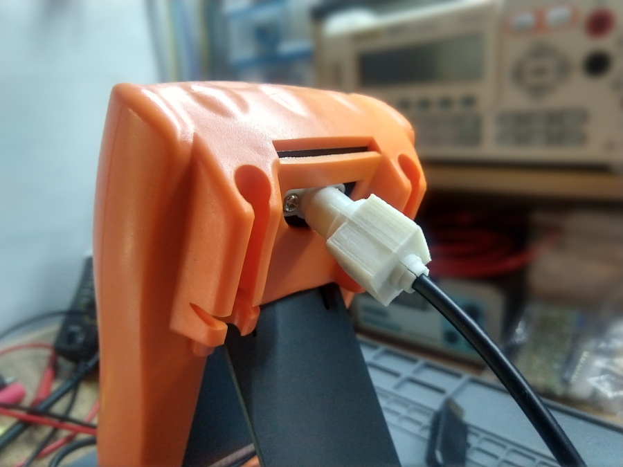
I’ve had a VC99 multimeter for a while, and one of the nice things about it, is that it can be hacked to give it RS232 output pretty easily.
The hack is possible because the VC99 uses a rather standard DMM chipset that has serial-output capabilities built-in. You can check if the feature is there by holding the REL key down for several seconds. The “RS232” indicator will appear in a corner telling you it’s sending data to its serial port.
The problem, however, is that the VC99 doesn’t have a serial port. But still, if you open the device and probe pin 92 (TXD) from the controller IC, you should be able to see the serial data being sent at 2400 bps.
The Approach
There are multiple ways of making a serial port out of that TXD pin, and give this cheap multimeter data-logging capabilities. One of the options is described in the chipset datasheet I linked earlier, and it’s basically an optocoupler IC connected to a physical RS232 port. Other people have been more creative and used RF transmitters, BT boards and ESP8266 modules to give wireless connectivity to this device.
Now, going wireless makes a lot of sense when you are linking a device that can be measuring hundreds of volts (like this multimeter) to something more delicate and precious (like your computer).
For my personal use however I don’t want nor need this to be truly “wireless” (i.e: free of wires) as there are many “issues” associated with wireless protocols and modules (They require pairing or negotiating the connection, can introduce delays in the system because of re-codification, encoding, etc, data wrapping, etc, they are more susceptible to data loss due to interference, they require more power from the multimeter, etc), so I’ve taken a page from the DER DE-5000 LCR meter and I’ve decided to make a REALLY short-range infrared link. And with “short range” I mean “the receiver photodiode will be pretty much sitting on top of the transmitter IR LED”-sort of short range.
The Electronics
So I started testing the idea by opening the multimeter and extending wires from the serial pin and the battery connector to a small breadboard.
For the transmitter (DMM) side, I connected an IR LED between a VCC pin from the board (used the positive terminal of the buzzer), and the serial data pin through a 1Kohm resistor. Normally that wouldn’t give enough current to make an IR LED bright enough to be detected by a photodiode at any sort of distance, but since the receiver with be basically face to face with the transmitter, this works great, even if the batteries are dancing around fully-discharged levels (around 2.1V).
For the receiver, I used a USB-to-TTL cable (like this one) and connected an IR photodiode between GND and RXD, with a 10K pullup to +5V.
The Connector
I then designed the connector system in FreeCAD and 3D-printed it. This process involved a couple of failed attempts, but eventually got a pretty solid connector and socket, with an interlocked barrel system.
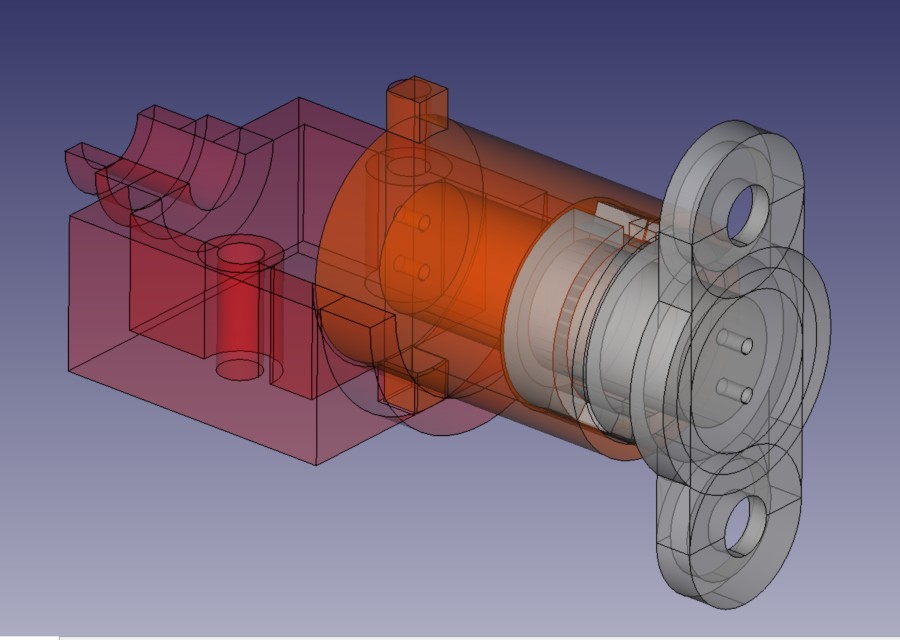
To install the multimeter-side connector you’ll need to drill a 6-8mm hole through the back plate for the LED legs and wires, and two smaller holes for the mounting screws. I designed the piece so it fits perfectly in the space left by D-shaped hole on the rubber protection.
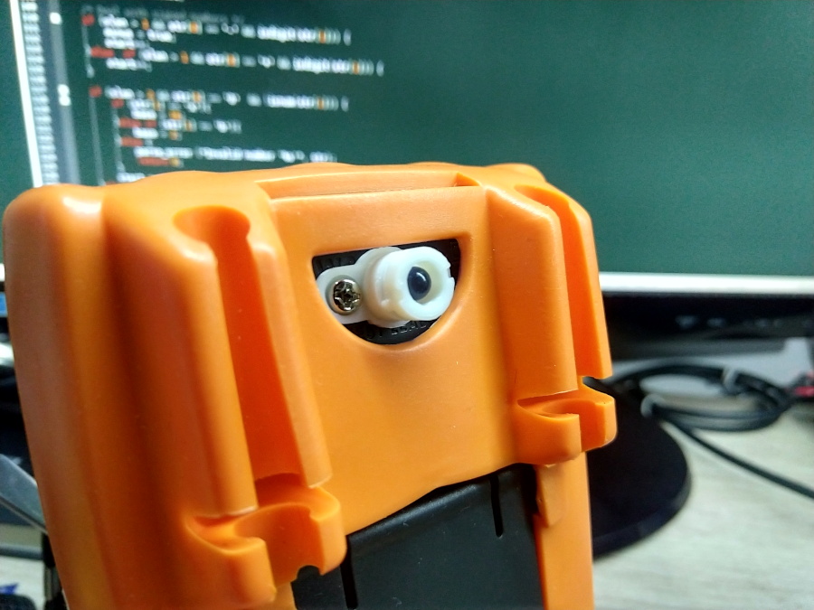
You already saw a picture of the finished setup at the top of this post, but I will give you a few more pictures of the connector pieces.
VC99 IR Link TX connector 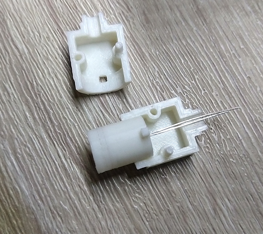
VC99 IR Link RX connector
I have uploaded the finished piece to Thingiverse if you are interested in 3D-printing one for yourself.
With this setup I can safely connect this instrument to my computer and log the measurements, and I can use this same connector I designed with other devices as a sort of personal standard around my lab for one-way electrically isolated communication.