 by
by As a break from my regular activities I decided to spend a week designing and building something with parts and components I’ve purchased over the years but never had the chance to use in a project. This is the result:
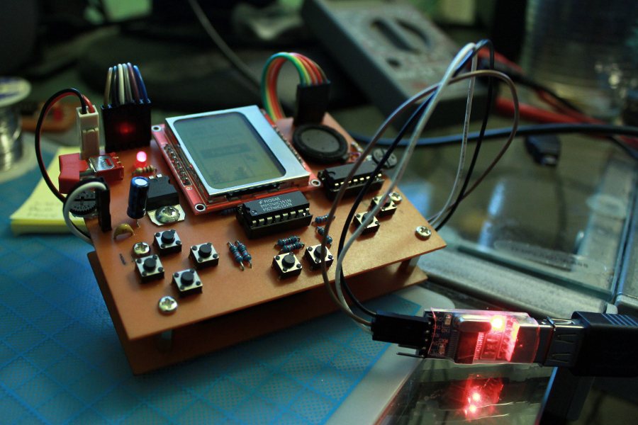
A sort of portable gaming device powered by a really old AVR microprocessor.
I’ll try to walk you now through the things I used to design and build both the software and hardware of this device.
The hardware
Arduino Diecimila

Although I’m a PIC (microchip) guy I decided to go with AVR for a change, so this Arduino board was the first thing I selected.
Please note that this board is from an early batch of a now-7-years-old Arduino model! It was bought for a project but tossed aside when the requirements changed.
Before I started this project I had almost no experience with the processor beyond quick-testing modules and sensors with libraries developed by others.
The ATMega168 on this board runs at 16 Mhz and has 1KB of RAM with 16KB of flash memory (aka “program memory”, PROGMEM or PGM) although only 14KB are available for “user code” since 2KB are used by the Arduino bootloader. This processor has been replaced in similar boards by the ATMega328p; a 100% compatible part from the same family but with 2x the RAM and program memory.
Nokia 5110-compatible LCD

I’ve been purchasing different LCD/TFT screens for the last couple of years so I thought it would be nice to use one of them now. Given the limited processor power on my Arduino I went with a small B&W LCD I bought from a fellow hobbyist once. You’ll find it on Sparkfun, Adafruit, Seeedstudio and probably other stores.
This LCD is driven by the PCD8544 controller, which is fairly simple to use.
Other parts
To power the device I hacked a cheap AA-powered “emergency phone charger”.

Using a 9V battery and a linear regulator (what most people do) is not the best idea. I mean it works, but Arduino requires 5V in the most common configuration and as little as 1.8V in a low-speed setting so you lose a lot of power (dissipated as heat by the regulator) when down-stepping a 9V battery to those levels.
Since at least 3.78V are required to operate the processor at >16Mhz I went with the classic 5V, which is what this “charger” provides (in practice it can’t pump out enough current for most phones, so it kinda fails at its intended function).
Luckily I never threw it away as it’s perfect for this project: It has no problem powering the arduino board, the LCD and the couple of ICs this project uses. I’m aware that boosting a battery to 5V just to power the microcontroller and then “stepping down” everything to 3.3V is still kinda inefficient, but it’s the best I could do with the things I had and still better love story than twilight than using a 9V battery.

For the game controls I picked a 74HC151N multiplexer which allows me to read up to 8 buttons with only 4 I/O lines from the ATMega chip and a thin piezo speaker (that I probably salvaged from a broken phone or toy) for the bleeps and bloops.
To convert the 5V signals from the Arduino to the 3.3V levels that the LCD accepts I used a CD4050 non-inverting hex buffer. I tried several other options but this was by far the most straightforward way to achieve a reliable conversion.
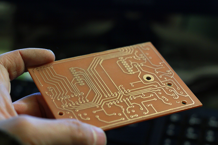
Although it looks kinda intimidating on a breadboard the circuit is quite simple (The schematic below also includes the 3.3V power stage and header connectors for all the signals that go straight to the Arduino board):

The Software
After I wired the LCD screen to the Arduino I used this code to test the display and make sure it was working properly. The example code in the page doesn’t show how to control the backlight but the only thing you need is Arduino’s PWM (Pulse Width Modulation) capabilities to drive the Backlight pin.
For the music I followed the tutorial on the tone() function and once I had a very basic tune player I modified the code to play the notes in an Interrupt Service Routine (ISR) at roughtly 40Hz so I could execute code in tandem with the music.
Since tone() interferes with PWM generation I was no longer able to control the backlight using the built-in PWM. To solve this I increased the frequency of the timer interrupt I was using for the music to around 8KHz and implemented pulse-width modulation by software (I also had to adjust the music code accordingly to wait 200 interrupt calls before processing the next note slice).
The backlight intensity is controlled by a trimpot and read with analogRead(), which is normally really slow on Arduino. Manually changing the ADC prescaler to 16 solves this.
As Arduino talks to the display controller via SPI I decided to use the hardware SPI bus of the processor to control the LCD (it’s way faster). I found a library for that (here) and heavily modified it to fit my needs.

Now, there’s a problem with the PCD8544 controller: Each column of 48 pixels is divided in 8-bit blocks so if you want to write to a particular pixel you have to write to the complete 8-cells array where the pixel is.
This would normally be a detail quite easy to deal with… except for the fact that there’s no way of reading the current contents of the VRAM, so if you want to write anything shorter than 8 pixels (or not aligned with the bank boundaries) to a certain location of the screen, you’ll overwrite the whole 8-bit block, succesfully erasing whatever it was in that 8-pixels rows first.
This of course is not good for games so I had to implement a framebuffer where all the graphic operations could be performed, and then -in every frame of video- dump the whole thing onto the screen. This gives me a lot of flexibility; I can read and write pixels from/to this portion of memory anytime and have total control of the way a new pixel or sprite is drawn on the screen.
Once I had the framebuffer in place I coded a basic set of routines and primitives (pixels, lines, rectangles, fixed-font text and bitmaps) for it. This also allowed me to re-map the screen space to my liking (my “virtual screen” is 48×84 instead of 84×48).
The only downside to this approach is that a 84×6 (6 banks * 8 bits = 48 pixels) framebuffer takes 504 bytes of RAM; half the available memory on the ATMega168, leaving very little RAM for games (~500 bytes shared with the stack and heap). To cope with this limitation I modified a few methods on my “framework” to read from the program memory space, so static data like music and bitmaps could be stored in the vast (16KB) program space instead of the almost-non-existent RAM.
To put this “console” to the test I implemented a small Tetris clone (although restricted to a 8×16 board instead of the usual 10×20).
Going Portable

Since the main board was already a standalone unit it was time to stop depending on the Diecimila board. Luckily creating an “Arduino-compatible” circuit with the bare minimum is quite easy.
Following the standalone Arduino tutorial I designed a board that includes the components required by the processor plus wires for the LCD, buttons and speaker on the other board. I also added the hardware to program this device as if it were an Arduino (although it now requires a USB2Serial TTL adapter like this one).
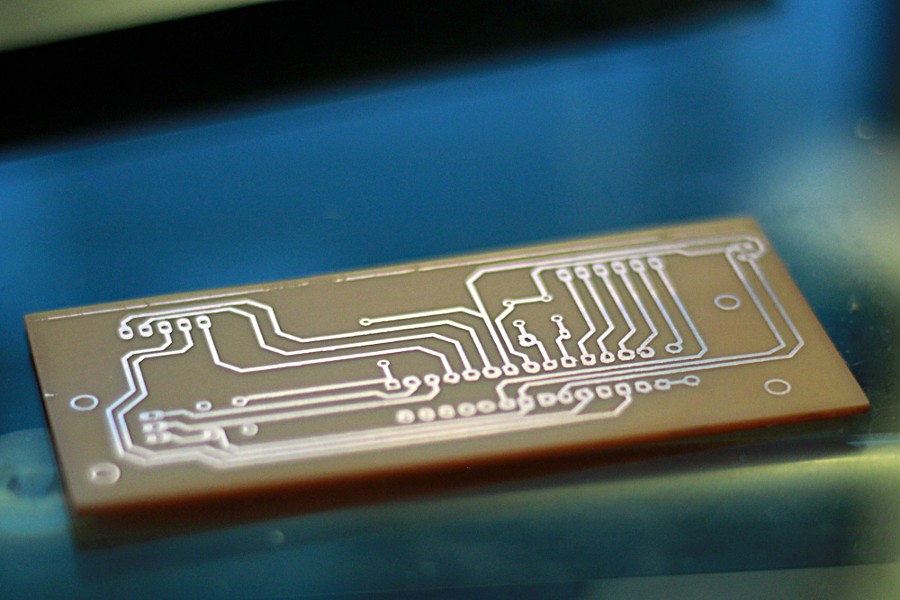
The control board that replaces the Arduino is REALLY simple:

With this new controller the finished device is basically a sandwich of 2 boards: the big mainboard on top, with most of the circuitry, and the small control board underneath, with the AVR processor and the few components it needs to run and be programmed.

I guess I could have made the whole device smaller by moving the level converter circuit to the bottom board, but I wanted the top board to be self-sufficient so I could -in a future- plug it to another processor or develop a more complex control board. There were also some usability concerns involved in the design: connectors and switches had to be located away from the bottom so they won’t interfere with the player’s ability to push the buttons, and the power switch and LED needed to be in the top board. This affected the layout considerably.
To Infinity and Beyond…

The whole framework and my implementation of Tetris (graphics, sounds and code) are less than 9KB in size so there’s space for more games in this “console” (Pong, Snake, Breakout and Space invaders are very good candidates).
I could also improve my Tetris with sound effects, more music, a hi-score table, etc.
I kinda want to experiment with faux grayscale (achieved by quickly switching between 2 black-and-white “pages”) but I’m sure it will make the framerate drop considerably.
Upgrades to the hardware are also possible: migrating to an ATMega328P processor or making a more complex control board with things like a tilt sensor for motion-controlled games or a SD card slot to further expand the program memory space (although both things are a bit of an overkill for such a simple device).
There’s a lot of room for improvement but for the time being I’ll leave you with a few more pictures of the process and the end result:


HI!
Can you send me a link with the source code of this tetris game?
Thanks!
Hi Fabio,
I actually never released the source code of the game nor the “firmware” of this device. I kept improving the code after I wrote this, and added other simple games, but the code was still a mess and decided to start an improved version of everything, which is something I’m still working on. So sorry, no source code :/
Very nice.. But my doubt is did you fully code for the tetris game or just ported from another platform like brick games…thank you..
Hi!
Wrote the code myself. I’m a Tetris lover and also it’s a very good “first” game to program on any new platform 🙂