As part of a bigger project (that I’ll reveal later) I set on the journey of designing a simple “keyboard”. It needed to have enough keys to be usable as a general purpose input device (so it requires alphanumeric chars, common symbols, ENTER, ESC, etc) and preferably built around components I already had (like the bunch of 6x6mm push buttons that I don’t seem to be using fast enough).
The Plan
Taking old devices and early computers as reference, I went with a 40 keys design (a 5×8 button matrix), arranged in a 10×4 distribution (internally 4 straight rows of 8 buttons, with the “fifth row” split into the 2 extra columns).
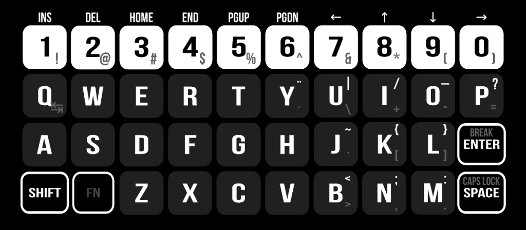
I spent some time doing a keyboard layout with Inkscape, trying to fit all the keys I wanted in a way that made sense:
I started doing some circuit designs for the project with multiplexers, shift registers, and binary counters to iterate over the rows, read the column data, and send the data serially to the “host” device, but the list of components and ICs was getting ridiculously big for a simple keyboard.
I wasn’t really keen on using a microcontroller because the idea of having a CPU on the keyboard that could potentially be more powerful than the host computer made me cringe, but even ridiculously old keyboards had a dedicated microcontroller inside so there was no real reason to avoid using one.
I chose a Microchip 16F628A processor, mostly because it’s kinda old, not really “high end” (partially appeasing my concern above), and can be configured to run with nearly no extra components (by virtue of its internal 4Mhz osc). It also has an on-board standard USART interface that I could totally use as the “keyboard port”, broadening the range of projects I’d be able to use this keyboard with.
It’s also one of my favorite old-school Microchip microcontrollers.
Coincidentally, this choice also freed me of using any kind of multiplexer or data shifter. With the proper configuration the 16F628 offers 16 pins (out of 18) as general I/O. Enough for the 8×5 matrix (13 pins), the serial communication port (2 more pins) and a status led (which I’m using for “caps lock”).
Hardware
I started doing the circuit design around the 16F628A, initially including diodes on every key to avoid ghosting issues, but I was having trouble getting all the buttons and diodes to fit within the limited board size available in the freeware version of Eagle (which is what I use to design my PCBs). Weather wasn’t cooperating with the idea of making a board from scratch either; We were enjoying a lovely weekend of heavy rain (safety first: Etching, drilling and sanding need to be done in a well ventilated area and I wasn’t going to open the windows with the winds and rain raging outside) so I decided to use some perfboards I had in my parts bin (a decision I kinda regret).
The boards were -however- also small in size, so selecting them for this project did nothing to solve the size problem I had. They weren’t big enough to fit the keys and the diodes in any distribution that made sense. As I wasn’t normally going to need more than 2-3 keys pressed simultaneously, and ghosting is something that can be “dealt-with” to some extent in software, I mounted the keys in the best possible layout the perfboard allowed, omitting the diodes.
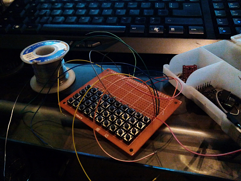
The thing with the 6mm switches that I used is that is nearly impossible to label the buttons in a simple way. You would normally need to create your own custom button “caps” for each one of them, and a custom case or keyboard cover to keep them in place.
If you are going to build a keyboard like this one, and you don’t have strict size constraints, I would recommend using 12x12mm push-buttons. They normally come in a design that accepts different kinds of already-available caps, including a very common square cap with a clear removable cover on top (under which you can insert a label that tells what the button does).
Ignoring for a while the potential problems with my choice of buttons, I hooked the matrix to a breadboard where I mounted the microcontroller, to finish the hardware design, making sure I was able to drive the thing properly before soldering anything else onto the perfboard. This is the final schematic:
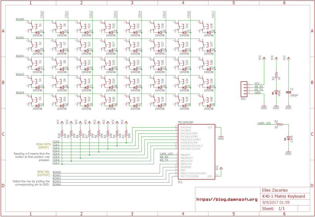
As you can see, I’m using RB3-RB7 to scan the rows, RB0 for the CapsLock LED, RB1 and RB2 configured as serial TX/RX, and the whole PORTA (RA0-RA7) is used to read each full row at once (with the expected pull-up resistors).
Who you gonna call? Ghost-..nevermind
I also wrote the firmware at this stage, dealing with ghosting by discarding the keyboard data when 4 or more keys are detected as simultaneously pressed. This limits the “polyphony” of the device to a maximum of 3 keys (minus 3-key combinations with a shared column over 2 different rows), but it’s enough for what I needed.
For a full explanation of what ghosting is, or how the diodes would have prevented it, please check PCB Heaven’s Excellent tutorial on key matrices.
The firmware I wrote also has 2 modes of operation:
MODE 0: In this mode the keyboard will send MAKE (press) and BREAK (release) codes for each key, just like regular keyboards do. The MAKE code of a key is ROW*8 + COL + 1, and the BREAK code is its MAKECode + 128. In this mode the host is responsible of mapping physical keys to “characters” and “symbols”. The meaning of each key is completely decided by the host.
MODE 1: In Mode 1 the keyboard acts like a serial terminal device, translating key presses into “characters” according to the layout I designed earlier. This mode takes into account the “SHIFT’ and “FN” keys I defined, sending uppercase and lowercase letters, symbols, special keys, etc. It also features a Caps-lock-like function, adapted to reduce the number of keys that need to be pressed simultaneously. With Caps-lock ON, every key reports its SHIFT-ed value when pressed, even the numbers (unlike modern keyboards, where CAPSLOCK only affects letters). Pressing SHIFT with Caps-lock ON results in the un-SHIFT-ed value of the key.
Additionally, the host device can issue commands to the keyboard to switch between the two modes anytime, query the active mode, and toggle CAPSLOCK at will (in MODE0 this only turns the LED ON or OFF, it does not affect the returned scan codes).
I may add an additional command in a future that allows the HOST to ask for the current state of any given row.
Putting it all together
When I was happy with the way the keyboard was working, I placed the rest of the components on the perfboard. The finished keyboard looks really good:
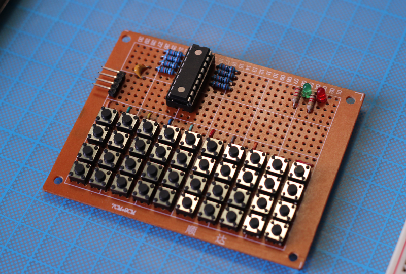
From the top, that is. The bottom side is a completely different story:
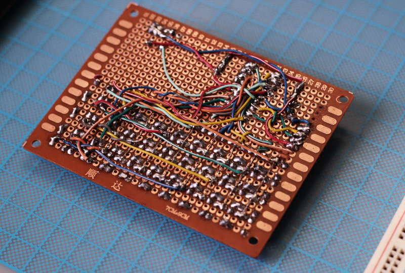
I’d be sure to remember next time to purchase stripboards instead of plain perfboards, because a lot of wiring and “bridging” would’ve been avoided had this board provided me with any connection between the pads.
It took me a ridiculously long time to solder and connect everything to this board, (cutting wires to size was probably the worst part) so I probably won’t ever use perfboards again for anything this “complex” (key matrices are simple in design, but require a damn lot of wiring).
Finishing touches
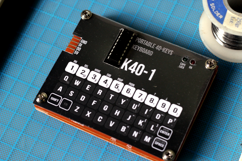
To “finish” this device, I adapted the keyboard layout I designed in Inkscape earlier so it would act as an overlaid screen (as if it were a membrane keyboard) and bought 5mm separators that gave just enough height for this screen to sit gently over the buttons. I purchased a regular thick plastic “paper sheet sleeve” and glued a piece of paper with the layout between the plastic sheets, cutting with a hobby knife a slot for the connector and space for the PIC:
And cheap.
Especially cheap.
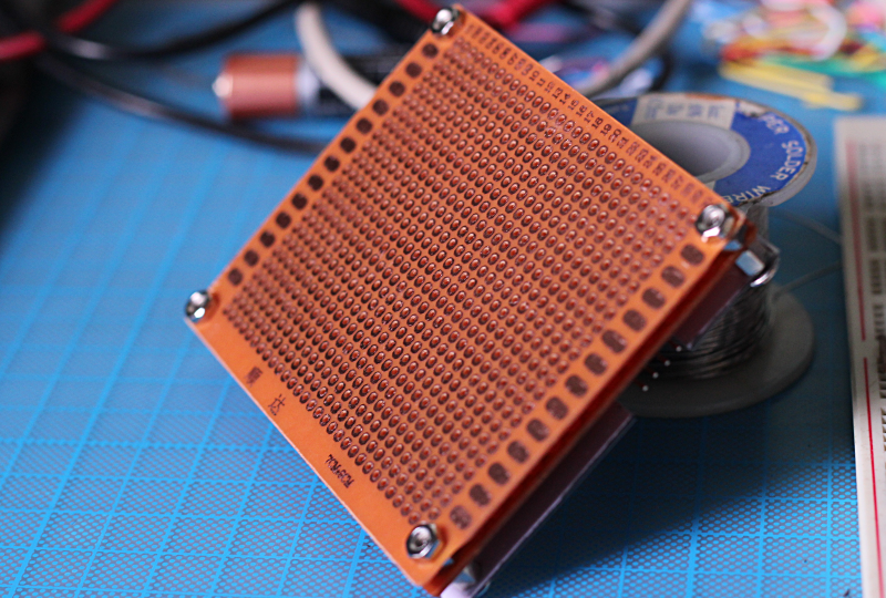
I also placed an extra unconnected perfboard at the bottom to protect the mess of cables underneath:
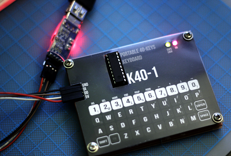
The resulting keyboard can be connected to any microcontroller or computer using standard TTL UART signals and can operate either as a completely layout-independent array of 40 keys (MODE 0), or as a general purpose terminal device where the key decoding and mapping is done on the keyboard itself (MODE 1).
I think the part I enjoyed the most was writing the firmware. It’s been a while since the last time I had to write assembly code for this kind of processor.
I’ll try to do a board layout for this device in Eagle (probably without the diodes, or perhaps with diodes only for the SHIFT and FN keys, so they won’t cause ghosting with the keys above them). Having done that, I’ll probably zip the whole thing (firmware, keyboard layout, schematic and PCB) and post it here. This would make a great open source hardware project.


Nevermind. 🙂 I realized if you set your rows to input (with pull-up resistor) then control the columns as outputs, I see how this matrix works.
Hi James,
Thanks for your feedback! It’s been a while since I made this circuit indeed! After your first comment I checked the drawing, and for a second I panicked too, because the diodes would indeed be backwards at first glance.
If you omit the diodes you can use either PORTA or PORTB as the input, thanks to the external pullups I added to PORTA, and the internal pullups already present in PORTB. Adding pullups to PORTA and using PORTB‘s internal ones is something I did a lot back then. With the diodes (as drawn), however, only PORTB makes sense as the input, but it relies on its internal pullups, which can’t be seen in the schematic. This asymmetry makes PORTA look as the input, which to be fair is something I probably intended at first (There’s some commented code in the firmware that seems to suggest that) but later changed.
I was not aware that my schematic was the first thing to appear on Google when you search for a keyboard matrix, and being this the case, it would be really good if the circuit worked in a more intuitive way, and did not depend on any knowledge of the PIC internals to understand how it works. Being a popular application, this schematic should be easy to follow, and should not depend on PIC specifics. It shouldn’t require an expert as yourself to see how it works. I will definitely update it so it’s independent of the micro-controller being used and it’s obvious at first glance how it works.
Thanks for bringing this to my attention!
I realize this is an old post or project, but it was the first image that came up on Google. I’m very certain the diodes in your schematic are orientated incorrectly. Biased in that direction would mean none of the switches are ever detectable.