by
by For a few months now (and after successfully using a cheap USB analyzer with my Pocket C.H.I.P) I’ve wanted to make a sort of standalone Logic Analyzer / mini linux machine that I could have on my bench. I originally wanted to use one of my C.H.I.P boards, but I soon stumbled upon a bit of a difficulty: It’s not that easy to use readily-available touch-screen / LCDs with the C.H.I.P.
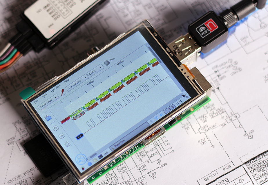
Because of this I decided to switch to an old RaspberryPi1 Model B that I had laying around instead. I don’t need anything faster than that, and finding TFT/LCD screens for Raspberry Pi is ridiculously easy. As a matter of fact, I already had a small 480×320 LCD that I tested before and worked really well. I may eventually switch to a small HDMI screen, but for the time being I’ll use this one:
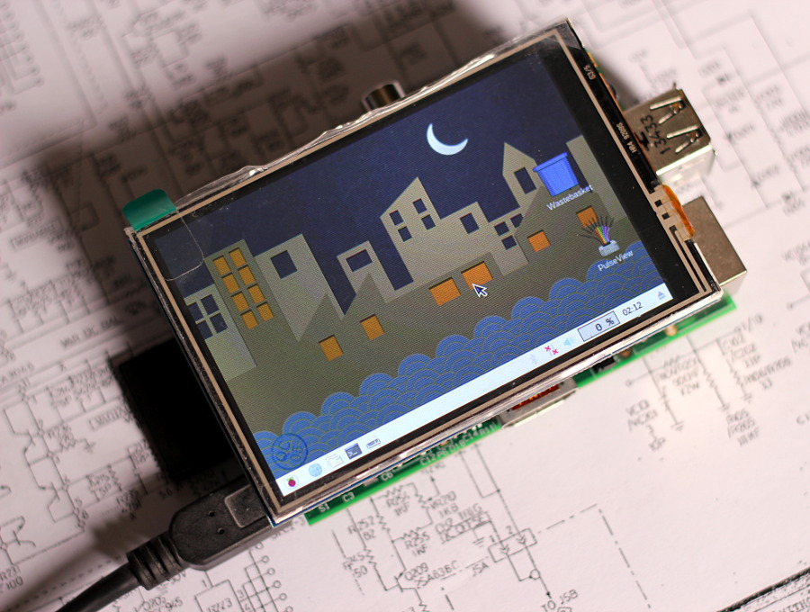
There are everywhere on eBay and similar sites and it’s pretty easy to make them work. Since they communicate with the Pi via SPI they are not particularly fast, and can’t take advantage of the Pi’s graphical acceleration*, so forget about running games, or watching movies with this thing (Not entireeeely true, but it’s not the best screen for that). They are more than enough, however, for small projects that require running Graphical apps.
Base Setup
Enabling Remote Access
I started with a fresh RPi installation and then enabled ssh access by running sudo raspi-config. This is optional but I find it easier to run commands from my computer using remote terminal. You’d probably also want to change your pi’s user password if you are going to enable ssh, and there’s an option inside raspi-config for that as well.
Installing the LCD
My TFT is a WaveShare 3.5(A) screen designed for a Raspberry Pi. You can install both the screen and touchscreen drivers following the instructions on Waveshare’s wiki, which basically tells you to download and unpack their driver package, run the appropriate script (in my case LCD35-Show), and then install xinput-calibrator to calibrate your touchscreen. You also need to enable (if it’s not already) the SPI interface with raspi-config, as that’s the “port” this screen will use. Once you have that working you should boot to the desktop on the LCD, and we can start tweaking its performance a bit.
Edit the boot config.txt file with sudo nano /boot/config.txt. Find the line near the end where the waveshare overlay is being loaded and add the speed and fps parameters:
dtoverlay=waveshare35a:speed=24000000,fps=60
I believe the default speed is 16Mhz, and some people recommend boosting that value well above 40Mhz which I guess could work in a RPi3, but definitely doesn’t fly with older hardware like my RPi1. With the Pi1 in fact you can’t even get to 30Mhz without getting messed up colors. I’ve found that 24Mhz works fine and gives a faster screen refresh rate.
Optional: Overclocking your Pi
Once you’ve done this you can overclock your pi with raspi-config. I could’ve done this a couple of steps before, but the LCD drivers overwrite /boot/config.txt and would have most-likely removed the overclock settings. The “high” 950Mhz OC setting works great, and you can even try with the 1Ghz turbo setting, but I recommend you to have a nice small fan inside the enclosure to keep the Pi cool.
UI Setup
Enabling right-click by touchscreen “long-press”
Having the option to right-click anywhere is always important, so we can enable a behavior that emulates this function whenever you press the touch-screen down for half a second. To add this run:
sudo nano /usr/share/X11/xorg.conf.d/10-evdev.conf
Find the touchscreen section near the end and add the EmulateThirdButton parameters so it looks like this:
Section "InputClass"
  Identifier "evdev touchscreen catchall"
  MatchIsTouchscreen "on"
  MatchDevicePath "/dev/input/event*"
  Driver "evdev"
  Option "EmulateThirdButton" "1"
  Option "EmulateThirdButtonTimeout" "500"
  Option "EmulateThirdButtonMoveThreshold" "30"
EndSection
Appearance Settings
To make the UI more usable at the tiny resolution of this screen I set the font to Dejavu Sans Extra-Light, size 7 (which for odd reasons is shown as “Verdana” later when you close this dialog) and also set icon size to small. These changes can be done by right-clicking on your Desktop and then selecting “Desktop Preferences” and should make most apps fit the screen when maximized.
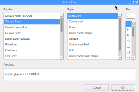
Font size 7 is quite small, and while I currently don’t have a problem reading it, I can see this setting not working for me in a decade or two, so take that into account. If you have not purchased a screen yet, I’d advise you to get a bigger one, as 3.5″ is a rather small size to fit a whole desktop with a puny resolution of 480×320.
I also enabled the option to shows currently mounted devices on the desktop, as it will be useful to have direct access to any flash drive I connect to import/export data.
Now that I was making changes to the UI I moved the taskbar to the bottom of the screen because in this limited screen space it makes more sense to me to read the title of the windows right at the top edge of the LCD, without the added offset of a “system” bar.
Screenshoter
To be able to take screenshots I installed xfc4-screenshooter with sudo apt-get install xfce4-screenshooter. This adds a shortcut in the System Menu under “Accesories” but I plan to write a script to automate this later.
Installing a virtual keyboard
The instructions from this site are great for adding a virtual keyboard to your Pi, especially the handy toggle script provided. They use matchbox-keyboard, but I think that xvkbd works better because it doesn’t push the other windows around when it launches, so I followed most of the instructions from that blog, but with xvkbd instead.
This means that I first installed xvkbd with sudo apt-get install xvkbd, and then created a toggle script with sudo nano /usr/bin/toggle-virtual-keyboard.sh with the following content:
#!/bin/bash
PID=`pidof xvkbd`
if [ ! -e $PID ]; then
  killall xvkbd
else
  xvkbd&
fi
Then made it executable with sudo chmod +x /usr/bin/toggle-virtual-keyboard.sh
After that, I created an entry in applications, with sudo nano /usr/share/applications/toggle-virtual-keyboard.desktop
[Desktop Entry]
Name=Toggle Virtual Keyboard
Comment=Toggle Virtual Keyboard
Exec=toggle-virtual-keyboard.sh
Type=Application
Icon=/usr/share/icons/gnome/16x16/devices/kxkb.png
Categories=Panel;Utility;MB
X-MB-INPUT-MECHANSIM=True
To also add an entry in the launchbar you can follow the instructions on the site, or you can right-click your taskbar, select Add/Remove Panel Items, Select the “Application Launch Bar” from the list, click on Preferences, and add your “Toggle Virtual Keyboard” application entry located under “Accesories”.
Customizing Openbox
We want most windows to fill the screen (with a couple of exceptions like dialogs, the virtual keyboard we just installed, etc) and hopefully not be bigger than our current resolution. For this I made a base configuration in Openbox that launches regular windows “maximized” by default (If they are reasonably well-behaved apps, this should make them fill the screen and cram all the UI elements inside the view if possible) and then added the exceptions I wanted.
To do this, edit the user configuration of openbox, which you can do by running nano .config/openbox/lxde-pi-rc.xml from your user folder. Then add the following rules after the <applications> tag:
<application name="*" type="normal">
  <focus>yes</focus>
  <maximized>true</maximized>
  <decor>yes</decor>
</application>

<application title="Screenshot">
  <focus>yes</focus>
  <decor>yes</decor>
  <maximized>true</maximized>
  <size>
    <width>100</width>
    <height>100</height>
  </size>
  <position force="yes">
    <x>0</x>
    <y>0</y>
  </position>
</application>

<application name="xvkbd">
  <focus>yes</focus>
  <maximized>no</maximized>
  <decor>yes</decor>
  <skip_taskbar>yes</skip_taskbar>
  <position force="yes">
    <x>center</x>
    <y>-bottom</y>
  </position>
</application>
The screenshoter “Pick an action” dialog is infamously big, and the best I could do was making sure it was going to start at the left top corner and use the whole screen. Even with those settings it barely fits and will require you to move it a bit to press “Ok” when taking a screenshot, at least when you launch the screenshooter via the System Menu. Since most of the settings can be selected from the command line it’s in theory possible to write a script that doesn’t show that screen and simply ask you where to save the image (we will try to do this later).
Rebooting the machine or logging out/in again should apply the changes.
Install Pulseview
Up to this point we’ve only made changes that allows us to use our RPi with the LCD for any task, like a general purpose linux machine. Now we will install the software we want to use.
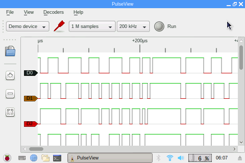
To install Pulseview Just run sudo apt-get install sigrok. You’ll also need to install the libqt4-svg package to make a few icons on the UI visible, as described in the update to my original post.
After it’s installed, we will create a Desktop icon for it. For that first grab the sigrok logo (or any picture you want to use, really) and copy it to your pi. I resized it to a height of 64px, and renamed it accordingly, because 512px was a bit excessive for the resolution I was using, but that’s optional. Put it somewhere in your filesystem (like a folder in your user home), then write a desktop shortcut. I did this with nano ~/Desktop/Pulseview.desktop
[Desktop Entry]
 Name=PulseView
 Comment=Logic Analyzer
 Icon=sigrok_64px.png
 Exec=/usr/bin/pulseview
 Type=Application
 Encoding=UTF-8
 Terminal=false
Set the path to the icon image accordingly. In my case I copied my modified image directly to /usr/share/pixmaps, so the full path was not needed. After this we can launch Pulseview from the Desktop and see how gorgeous it looks:
Using the openbox config file described a few steps above you should be able to get even more screen space by setting Pulseview to run without the Window borders to better use the screen space. For that you’ll need an <application> entry exclusive to Pulseview, and set its <decor> to no. Like this:
<application name="pulseview" type="normal">
  <focus>yes</focus>
  <maximized>true</maximized>
  <decor>no</decor>
</application>
If you also set the taskbar to auto-hide (as we will do later if we add a hardware button to launch the keyboard) you should have even more screen space. Pulseview is already usable at this resolution (and even at slightly lower ones, like in the Pocket CHIP) but generally speaking you want to have as much of the program on screen as possible.
Other software-related changes
I removed several packages like games and development tools I won’t be using on this device, and changed the wallpaper to a smaller image to hopefully make the desktop load a bit faster on boot, but none of that is really needed.
Hardware changes
A problem with the early RPis (that was corrected in later revisions) is that if you connect any device to your RPi that causes a current draw spike even for a fraction of a second, your RPi will reboot. This makes hot-plugging USB devices a bit of a problem. If you are using an old Pi like me, one alternative to cope with this is adding a USB-hub that can be powered externally, and add a separate power supply for it inside your project’s enclosure. Another alternative is to follow the advice of this blog post, and solder an additional >200uF capacitor to the USB cap already in place:
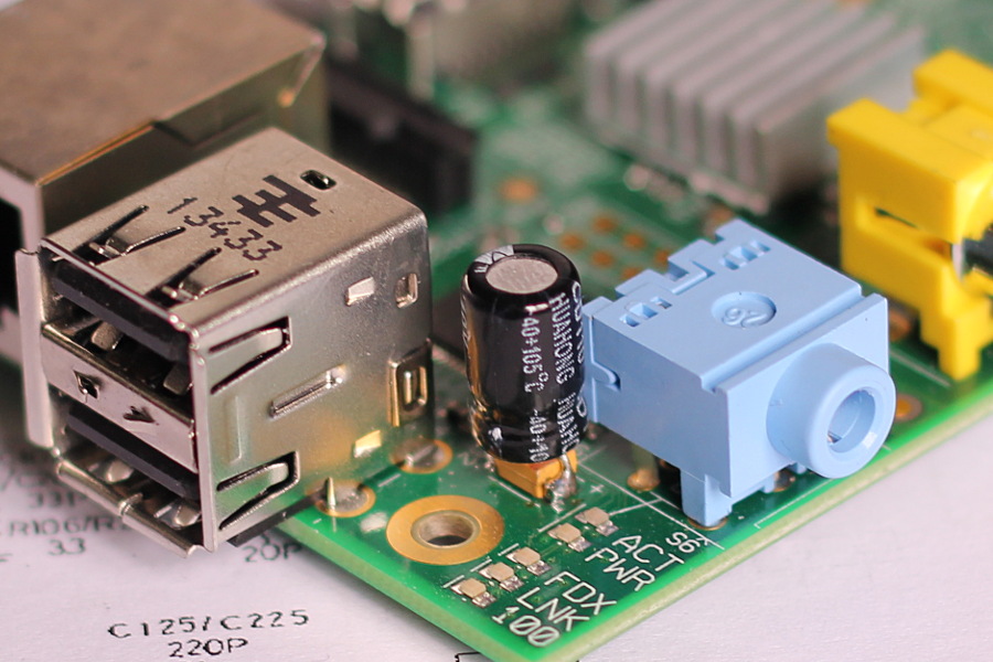
This doesn’t solve the problem with particularly power-hungry devices (like my mini wifi adapter), but works great for flash drives, wireless keyboard receivers, etc.
Solving other issues (From my setup)
Talking about my wifi adapter; I’ve been connecting this Raspberry Pi to my wireless network with this very tiny and cheap USB wifi dongle that I keep around, and it normally works great, but with the Pi it was dropping my remote shell connection quite frequently after a few minutes of inactivity. This led me to believe that it had some sort of power saving mode and it was probably better to disable it. I will not keep this Pi constantly connected to internet, but if I eventually want to remote this machine or install packages on it, I’d rather have this working properly.
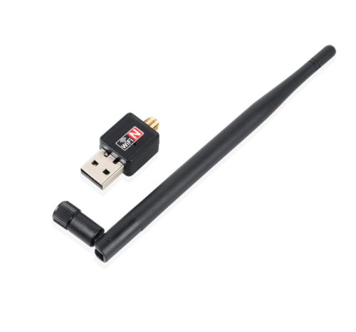
I Googled the issue and apparently the driver used by this wifi adapter (8192cu) has a power management setting that is on by default. If you are using a similar adapter you can check this with:
cat /sys/module/8192cu/parameters/rtw_power_mgnt
Surely enough the output of that command is “1”, meaning that it’s enabled. This forum post details how to fix it by creating a config file for the driver with sudo nano /etc/modprobe.d/8192cu.conf with the following content:
# Disable power saving
 options 8192cu rtw_power_mgnt=0
After rebooting the power management mode should be disabled. You can use the same command as before to check. This solved my connectivity issues with my wifi adapter.
Next Steps
I will definitely build an enclosure for this project in Part 2, and will add hardware buttons for “quick access” to several functions. For the time being this crude setup works and allows me to have the logic analyzer with me at all times in my lab.
BONUS: Installing fbcp
There’s actually a way of solving many of the screen related problems with these tiny LCDs, but I did not want to discuss it until the end of this post because it’s not really that straightforward, and depending on what you want to do, may not even be needed.
With the configuration we’ve done so far, graphics are rendered directly to the TFT screen framebuffer, skipping the graphic capabilities and composite/HDMI output of the RPi. The LCD driver has no hardware acceleration whatsoever. This means that any software which opens a GL-enabled context for rendering graphics will not work on your TFT and will output the video directly to the onboard graphics chip, and not your TFT.
If you want to take advantage of the graphics acceleration of the board, and be able to see GL-rendered content on the TFT (like 3D visualizations, or games) you’ll need to install fbcp (framebuffer copy) which configures the Pi to run on the HDMI output, and continuously copy the video memory to the TFT. This shouldn’t be slower than directly rendering to the TFT framebuffer, as the hardware-accelerated output works pretty much on its own, and fbcp will have the same workload as we had before, because the amount of pixels to be transferred to the screen is the same.
This method has the added benefit of providing simultaneous HDMI output that mirrors the LCD, which could be handy to capture video footage of your debugging sessions, or to connect your analyzer later to a larger screen in your lab.
To get this working we first need to set the HDMI resolution and adjust several other parameters. This can be done in the /boot/config.txt file, adding the following lines:
hdmi_force_hotplug=1
disable_overscan=1
hdmi_cvt=720 480 60 1 0 0 0
framebuffer_width=720
framebuffer_height=480
hdmi_group=1
hdmi_mode=2
The “group=1, mode=2” settings means 720×480@60fps, 4:3, which is the smallest resolution closest to what our screen has, and will be the resolution of the HDMI output in our setup. For a list of other options check Raspberry Pi’s documentation on video modes.
The framebuffer size is set independently, and will be down- or up-scaled to both the HDMI monitor output, and your TFT. I selected 720×480 which is the same as our HDMI output, and has the same aspect ratio than our TFT has (although it will not be shown entirely on a HDMI monitor unless you enable overscan, because HDMI only knows 2 aspect ratios: 16:9 and 4:3, and this resolution is neither of those despite being a standard setting). With a 4:3 or 16:9 LCD this should not happen.
Enabling overscan will make the screen fit the HDMI output perfectly, but will show a black border on the TFT, wasting pixels from the little screen space we already had. For this reason I disabled overscan: I’m trading missing borders on the HDMI output for full-frame TFT image.
With these settings our graphical environment will run at 720×480, which is plenty of screen space for most apps, so 90% of the modifications explained in this post to make things fit in the tiny 480×320 space won’t be needed. The LCD still refreshes at a decent rate for general use, although there’s a bit of “lag” between what you see on the HDMI output and the LCD, which is the time it takes for the the full video frame to be rendered, resized, and transferred to the TFT screen.
Lowering the requested resolution and buffer size should help a bit, but the real bottleneck here is the amount of pixels that need to be transferred to the screen. A lower-res LCD should actually work better, and that’s what people normally recommend in similar setups if you want to run games. A 320×240 LCD for instance would require half the amount of pixels to be transferred, and would allow you to set your HDMI output to 640×480 which is still a good standard resolution in an accepted 4:3 aspect ratio.
Anyway, let’s continue. The next step is to compile fbcp and for that we can follow a handy guide from the retropie community. The relevant part for us is the following:
sudo apt-get install cmake
git clone https://github.com/tasanakorn/rpi-fbcp
cd rpi-fbcp/
mkdir build
cd build/
cmake ..
make
sudo install fbcp /usr/local/bin/fbcp
Then we want to make fbcp run at startup. There are many ways of doing this, and plenty of suggestions online that seem to work in newer devices, but since the stock kernel on an old RPi doesn’t seem to load device overlays quickly enough, most of those methods failed for me, as fbcp needs to be called after both framebuffers are working. The new distributions of RPi seem to use systemd for controlling the boot sequence, of which I know very little, and I only had limited success running fbcp via that system at a few points during my tests (managed to make it work, but it took like 2 minutes to start after every reboot), so I gave up and went back to the simplest method, but hacked something that works for me.
For that I modified the rc.local startup script with sudo nano /etc/rc.local and added the following line before “exit 0”:
until "/usr/local/bin/fbcp"; do sleep 1; done &
Yes, that’s a loop that will try to run fbcp every 1 second until it succeeds. Ugly, but it works.
Next we need to tell X11 to run on fb0 (the native framebuffer) instead of fb1 (The TFT). This is something that the LCD install script most likely changed, and we need to change back. For this run sudo nano /usr/share/X11/xorg.conf.d/99-fbturbo.conf and make sure it uses fb0 now:
Section "Device"
 Identifier "Allwinner A10/A13 FBDEV"
 Driver "fbturbo"
 Option "fbdev" "/dev/fb0"

 Option "SwapbuffersWait" "true"
EndSection
You may also want to switch the console back to fb0 with con2fbmap 1 0
After all of that reboot the machine and you should get a 720×480 screen that supports hardware-accelerated graphical contexts, downscaled to your TFT, and simultaneously mirrored to the HDMI port. A bit of a side benefit of this, is that the LCD will never show the boot console data, as fbcp will be loaded after the system has booted, and will be unloaded right before it’s shut down, making this device look more like a proper machine.
Running fbcp alleviates most of the problems with the resolution, so perhaps upgrading this project to a larger HDMI display won’t be needed after all, unless you want faster screen updates and smoother operation.
If you are using a more powerful Pi that can run games and 3D software like a RPi3, it would make sense to use a better screen, but for an old model like the one I have I think this screen is more than enough, with or without fbcp.