 by
by I love DIY/soldering kits, and thanks to online marketplaces like eBay I’ve been able to purchase and assemble a number of them for the past few months.
One of the last ones I got was a very basic but useful function/signal generator, whose only problem was that it required a power supply with +12V/+5V/-12V rails (it also arrived already assembled despite being sold as a DIY kit, which was disappointing in a way).
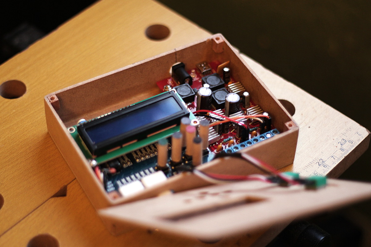
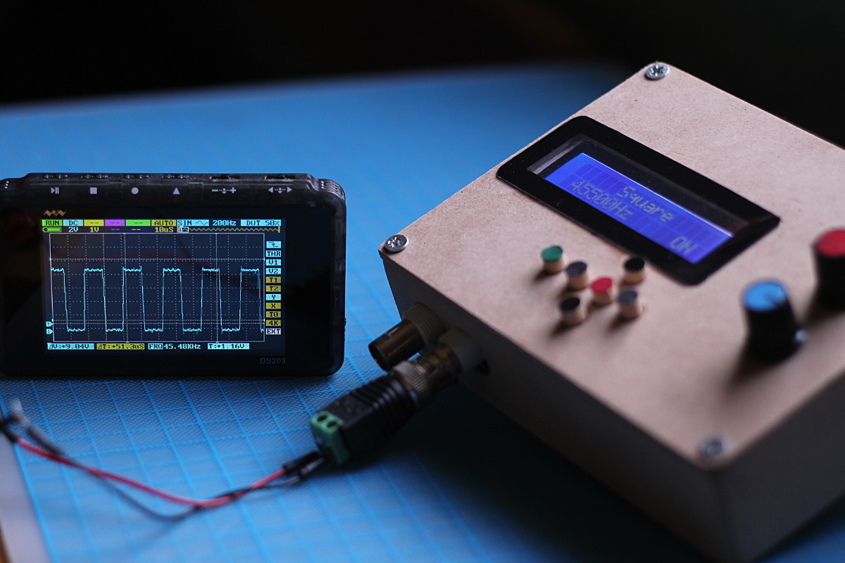
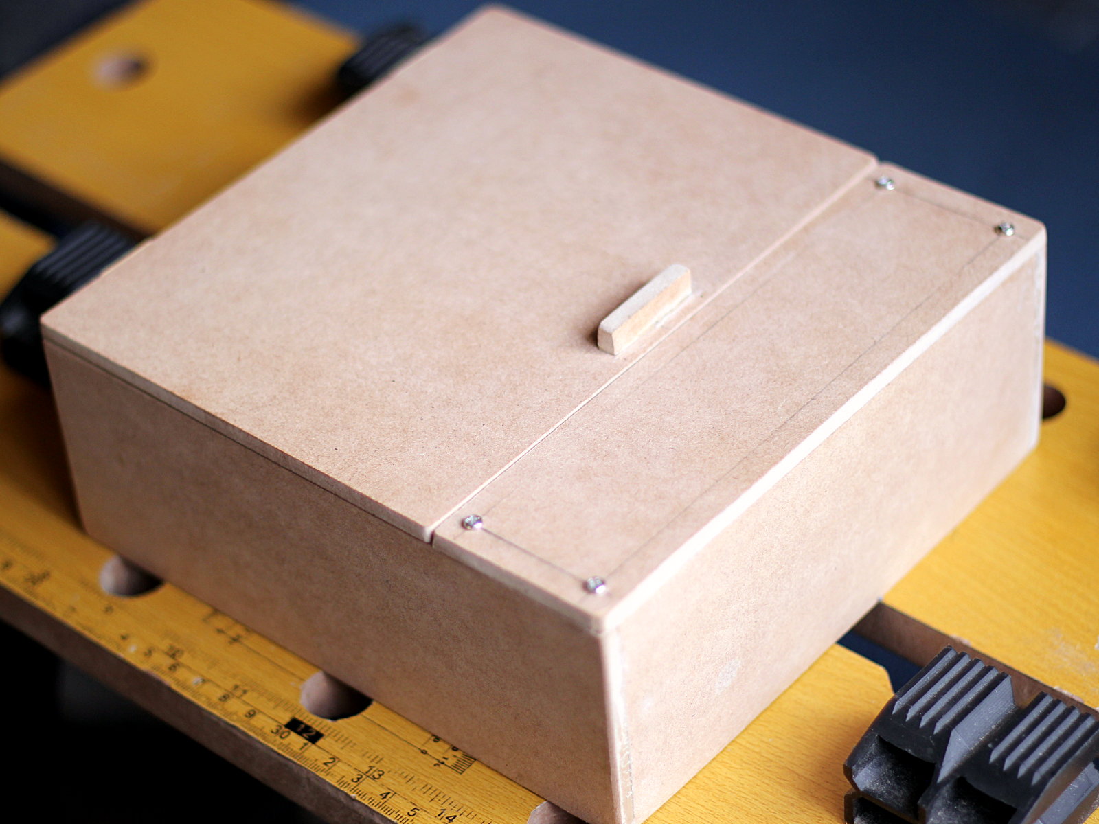
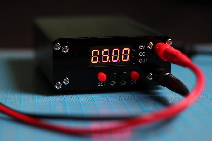
My firsts tests of the kit were with a PC power supply (the only source of -12V I had in my lab) until I got a “proper” alternative in the form of another kit, which is sometimes advertised as a “Hiland USB Dual Power Multiple Output Supply”. I will call it HL supply during this post (Mine says “Hyland” on the PCB, so assuming an original version exists mine is probably a cheap clone). This one actually required assembly (yay!) and worked fine in my limited tests, but it was still a hassle to have the two boards dangling around connected whenever I wanted to use the signal generator, so after some time I decided to make a (temporary) enclosure for the whole thing.
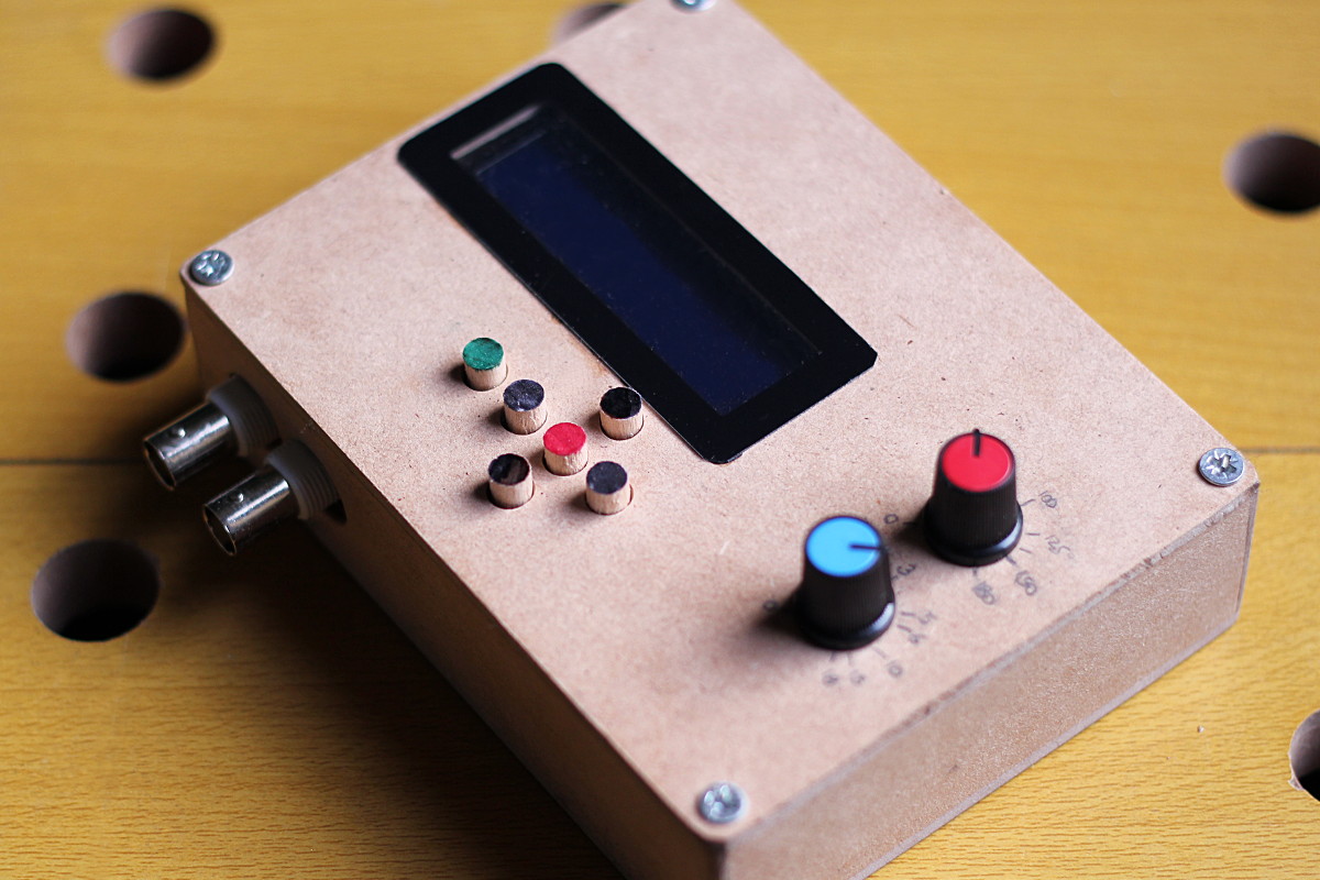
Despite not looking particularly good, the box is at the very least able to contain both things in a rather practical form factor, so for the time being I’m happy with this. It was also fun to build, so …there’s that.
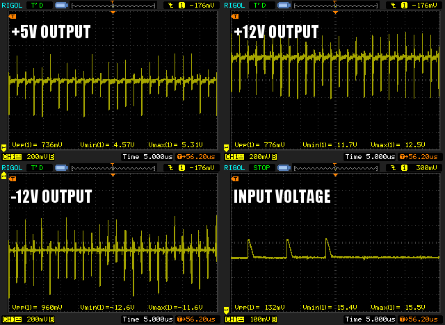
Once assembled, however, I discovered a problem; my Rigol oscilloscope was struggling to continuously trigger on the generated waveform. It was a bit unstable, especially with non-square waves. While this kit never gave a 100% clean signal (and don’t recall if I had tried its output on this particular scope before) the trace was just too noisy, so I started suspecting that the power supply was at fault. Either the HL kit itself or the variable DC-DC booster I was using as a voltage source. So I hooked the power supply alone to the oscilloscope and to my surprise this is what the relevant voltages looked like:
Just a guess.
Well that looks awful. While my DC-DC booster has some 100mV spikes here and there (bottom-right) the outputs from the HL Supply were all over the place, sometimes with differences close to 1 full volt peak to peak. To be sure this wasn’t completely caused by the spikes on the input I tried with a standard 12V wall transformer (instead of my booster @15V), and the nasty noise was still there, just ~100-200mV lower, which was still a lot.
So I then tried again, but using the USB jack on the HL board, directly connected to my computer instead of a 12-15 DC source:
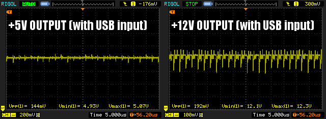
Almost 200mV of noise is still a bit too much, but it’s better than the ~700-1000mV I was getting with my switching booster set to 15V, or the ~500-700mV from the 12V wall adapter. I also tried with my bench supply, and noise was a bit lower, but just as I thought, it also went down as the input voltage decreased. In no test however I got less than ~150-200mV, even with my best and most stable supply set to +5V, so noise was definitely dependent of both the stability of the input and its voltage, with a lower floor of around 150mV.
I don’t know if I got a faulty unit or this is to be expected from the HL kit; all I know is that for a signal generator this was a rather unacceptable level of noise, so I decided to design my own multi-output supply, a task a bit out of my comfort zone, as I almost exclusively design digital logic circuits, and my “power supply” circuits have never been more complicated than a linear regulator and a few caps.
The “challenging” part of course was going to be the negative voltage output, that according to my tests needed to be capable of at least 50-70mA of current (as that’s what the function generator draws from the +12V and -12V inputs). This meant that I couldn’t just use a ICL7660S, which to my understanding it’s only capable of 20mA.
Luckily enough I stumbled upon this old but quite educational video from EEVBlog which goes through all the steps of designing a DC-DC regulator using the popular and versatile MC34063 IC. He follows through with the booster configuration, but the steps are pretty similar (just different formulas and different arrangement of the components) for getting a negative supply out of the IC, and all the information is right there in the datasheet.
With this knowledge I designed a circuit that takes a >13V input, regulates it to +12V DC using a standard LM7812 and then powers a LM7805 (which creates the +5V output) and a MC34063 configured to invert +12V into -12V at ~150mA, creating the -12V rail with enough spare current to make this a more general purpose supply. I prototyped this on a breadboard, and after getting all the outputs needed I moved it to a piece of perfboard that I cut to size to closely follow the HL supply footprint, so I wouldn’t need to modify or redo the enclosure.

After testing the whole thing I was still getting >100mV of ripple in the negative output despite calculating all components for a max of only 50mV Vpp “noise” . This was even with the optional filter suggested by the datasheet.
Since I had selected most components (except for the timing stuff) with some headroom, and I had a potentiometer on board for fine-tuning the negative voltage, I decided to adjust the -12V output to around -13V, so I could put that through a LM7912 negative linear regulator as a final step. Of course since I picked the components for a -12V output the circuit was now running a bit outside of the specs I designed it for, so I’m probably not getting the 150mA max output I desired, but at least I got now a linear device that takes care of the extra noise. With this modification these were the outputs of my supply when analyzed with the oscilloscope (These pics are with a Y axis scale of 50mV per division instead of 200mV):
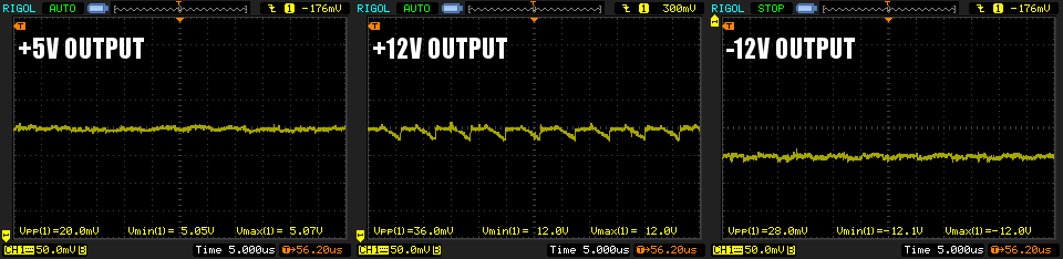
Sure, it’s not perfect, but it’s a massive improvement over the HL supply. <50mV of ripple is at least 3 times better than the “best” I could ever get out of the other supply. Now, being fair I think that the HL module is still ” fine” for most uses despite the unstable output. The noise frequency is very high (well above 200Khz) so most devices won’t really care. It was just that the artifacts were too visible in my bench scope and caused a glitchy and noisy trace, and for this particular use (a signal generator) you want the cleanest waveform you can get.
I really learned a lot designing the power supply. It required some research on switch mode regulators and negative voltage outputs, and I’m pretty happy with the result. This was also a good exercise on finding a problem and creating a drop-in replacement part that solves the issue while requiring no modification of the end product.
Bonus Picture! This is what the bottom of the ” buttons” of my enclosure look like in case you were wondering:
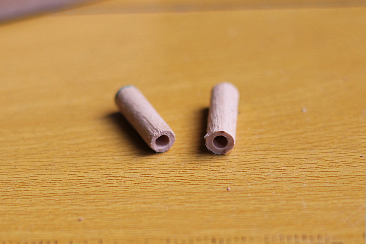
They fit and work surprisingly well.


Hey Elias,
I am responding to you post ” Power supply for a DIY function generator kit”.
As i am dealing with exactly the same issue i am very curious about your design specs.
I was hoping to see them in your post, but it wasn’t.
Now ofcourse i looked at Davids blog post you referred too, that and others specifically on the ripple issue.
So concerning the above i have two questions.
1: could you share your design specs?
2: besides using the mc34063 instead of the lx6008 the hyland uses it seems to me that the build-up of the hyland is pretty similar (exceot that the hyland has additional -5V and +3V rail) . Since i also use it for the same and exact wave generator i don’t need these really. so i was wondering if it is possible to modify the hyland board to use the mc34063 instead.
any help would be greatly appreciated!!
Kind regards
Matthieu
Hi Matthieu,
Unfortunately I no longer have the circuit and never drew an schematic. Back then I wasn’t as rigorous as I am now. My “design”, however, was just the standard MC34064 circuit you get from the datasheet, with components selected to get ~-13V, plus a bunch of linear regulators (78xx for the positive outputs, 7912 for the negative rail) and capacitors to stabilize the output.
Now, I should have done this before (to troubleshoot the supply instead of replacing it), but I just Googled the schematic for the HL supply, and it seems to be pretty similar to what I did. Maybe your idea of modifying the HL board could work, but it’s also quite likely that maybe a pair of carefully placed capacitors would improve things greatly, given how straightforward each voltage rail is.
Regards! (And Happy New Year)