by
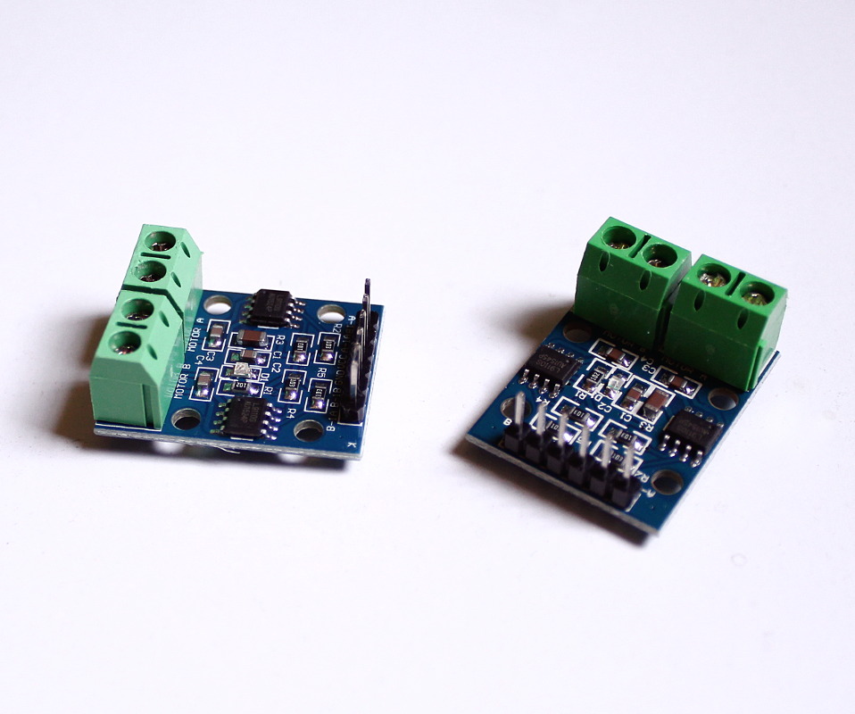
by So in the sort of tutorial I wrote about ORC-KIT I mentioned that it was possible to use other boards instead of Adafruit’s friendly motor shield, and in fact, there was space in the board for a couple of very cheap and widely available L9110S Dual H-Bridges, which should give you more control over the build, and “free” some precious Arduino pins that you can use for extra sensors and actuators. You can actually change the Arduino for something else, but that’s beyond the scope of this post.
H-Bridge?
H-Bridges are simple circuits that allow you to control the flow of current through a “load” with 2 control signals (A and B). When the load is a motor, you can make it spin forward, reverse or stop completely by changing the digital values on A and B. H-Bridges normally have an ENABLE line as well, which you can toggle yourself or leave permanently “ON”. Controlling the speed of the motors is easier if you can turn each bridge on and off quickly using PWM pulses applied to the enable lines, but that’s not always possible. The L9110S boards don’t have an enable pin, for instance, so we will need to manipulate only the 2 basic control signals to drive our motors if we use this controller.
Individual controllers vs the Motorshield
Under the hood, even Adafruit’s motorshield uses 4 H-Bridges, but it adds extra circuitry for storing the control signals in an 8-bit shift register. This allows the board to set the control signals of each H-Bridge with only 4 pins, and leaves the speed of each motor to be controlled with PWM pulses on the 4 ENABLE lines. In total the board requires 8 pins from the microcontroller, but only 4 of them need to be PWM-capable. As the physical board doesn’t leave the unused digital pins “exposed” in a header, there’s nothing you can do to use them with ease. You are stuck with the 6 pins from the analog port, which should suffice for most applications, though.
Using 4 H-Bridges directly in your robot will also require 8 pins from your microcontroller (add 4 more if you have (and want) control over the enable lines), and while it seems there’s no advantage to this approach, there are several optimizations and compromises you can do based on the physical properties of your build, that you cannot do if you use the motor shield.
For instance in a 4WD (4-Wheel Drive) robot, the 2 motors of one side will normally spin in the same direction, so in theory you could use only two H-Bridge controllers with the motor output of each controller connected to the motors of that side in parallel, or alternatively 4 H-Bridges with the control signals of the same side connected to both controllers at once. With either option you reduce the needed pins to 4.
Dealing with H-Bridges directly without a “friendly” controller like Adafruit’s motorshield should give you more room to play with and more options for customizing the build, but it’s way harder to manage, and you’ll soon see why.
Implementing the same features
Ideally we’d like to have the same amount of control and features of Adafruit’s board, so we can switch from one option to the other without losing features or having to rewrite our code.
Converting the currently implemented control scheme to the raw control signals required for the H-Drivers is easy, as internally the Adafruit motor shield uses H-Bridges, and the only difference is that with the shield instead of setting the signals directly we feed that data to a shift register, which is something we won’t need to do here. The problem is the speed-controlling mechanism, which we need to implement ourselves. If we had access to the enable lines of the H-Bridges we could do what the Adafruit controller does, but since this is not always the case (and because we don’t want to use a high number of pins either) we’ll need to find another way. An alternative method of achieving this is by PWM-pulsing the A and B lines of the bridges, and we can do this in software with Arduino’s hi-res timer (Timer1) by creating a high-frequency interrupt that triggers several hundred times per second, which can then be used to create the required pulses.
Creating a timed interrupt with the Timer1 library is as easy as this:
void pwn_proc() {
  // Check current time slice. Compare against required speed per motor,
  // turn their control lines ON or OFF as required
}

...

void setup(){
 ...
 Timer1.initialize(150); // interval in microseconds
 Timer1.attachInterrupt (pwn_proc);
}
If you are wondering why not using Arduino’s built-in PWM pins as Adafruit’s motor shield does, the reason is fairly simple; Unlike with the motorshield, we are working with no access to the enable lines of each bridge, so we need to pulse (depending on their direction) the A and B lines of each motor instead. This means that for 4 motors we should be prepared to generate a PWM pulse in any of the 8 different pins being used for that, and Arduino has only 6 PWM-capable pins. Servos also use PWM so if you want to have 2 servos like the Adafruit board has, you’ll need a total of 10 PWM-capable outputs, and we just don’t have that.
Doing this by software works, but the problem we have now is that Timer1 is used by Arduino’s analogWrite() which is also used by the servo library internally. By using this timer ourselves, we break the standard Servo library. To solve this newly created problem, we will need to generate the servo signals by hand as well, while hopefully providing a “Servo lib”-equivalent interface. The servo control pulses are normally short but need to be refreshed each 20ms. You can use Adafruit’s SoftServo library which generates the servo pulses directly, but keep in mind that it requires you to constantly call their refresh method() each 20ms or less.
This can actually be automated by taking advantage of the processor’s other timer: Timer0. This timer is configured by Arduino’s framework with a frequency of 1ms and is used by functions like millis() and delay(). Without messing with its settings we can create a “hook” function that uses the CMPA trigger to execute itself every 1ms, and in this procedure we can update our servos every 19 or 20 calls. This is done with the following code:
SIGNAL(TIMER0_COMPA_vect) {
  // Count the calls to this function.
  // Refresh your servos each 19-20 calls
}

...

void setup(){
 ...
 // This enables a COMPARATOR on Timer0, which will trigger
 // when its counter reaches a certain value.
 OCR0A = 0xAF;
 TIMSK0 |= _BV(OCIE0A);
}
Do-It-Yourself … or not.
Of course you can do all of this yourself, but I’ve recently added to the ORC-KIT Arduino code an H-Bridge driver that is fully compatible with the previous Motorshield controller and implements everything I’ve mentioned so far in this post. To use the H-Bridge driver with any of the examples, or your own code, you only need to change the #include <ORC_motorshield.h> line in the sketch for:
#include <ORC_hbridgedrv.h>
That’s it. There’s a pretty clever system in place to make switching between both controllers as easy as that.
Inside ORC_hbridgedrv.h you’ll find the pin mapping for the H-Bridge driver configuration, and you will probably also notice that the init() function can receive a parameter that is not present in the Motorshield version, which is the number of motors you want to control (up to 4). With this you can reduce the number of pins used by the controller if you only need 2 independent H-bridges.
My implementation of the H-Bridge driver also includes my own version of a software-based servo controller, similar to Adafruit’s SoftServo but with the full range of functions supported by the official Servo library, plus a method to manually adjust the signal timing and motion range in case you have a non-standard servo. Check ORC_softservo.h for details.
To compile the code with the H-bridge driver you’ll also need to install the TimerOne library either from within the Arduino IDE (Sketch->Include Library->Manage Libraries…) or from its github repo.
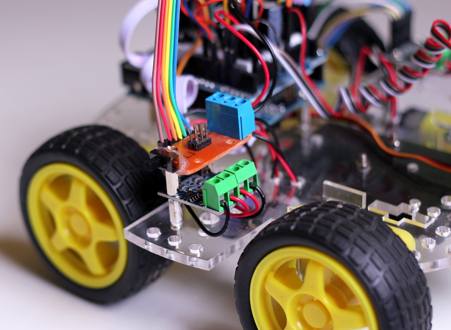
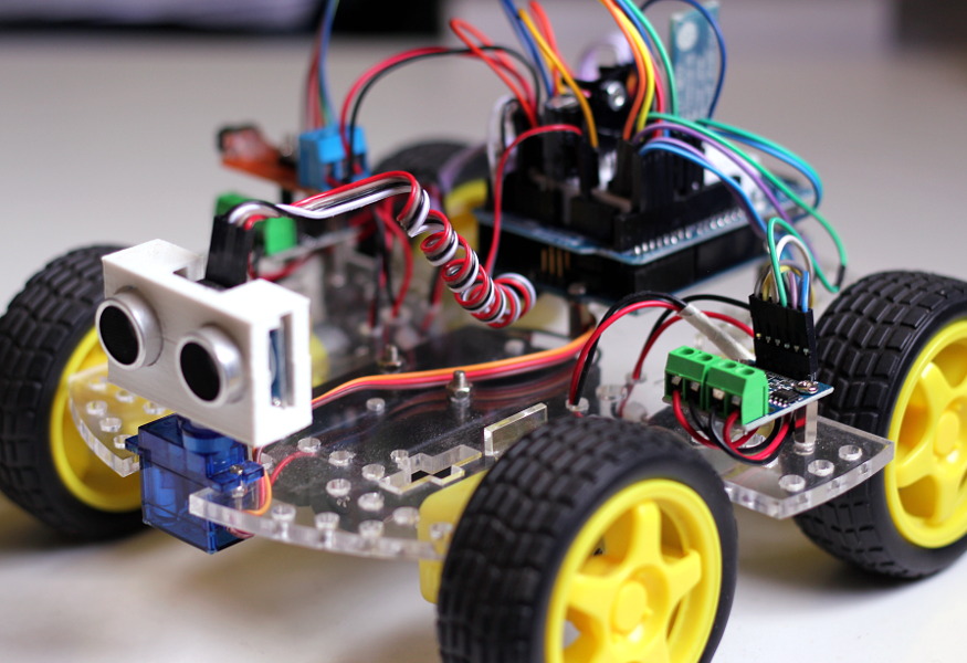
I also modified my robot to use the H-Bridges to test the code, so here is how it looks:
Please bear in mind that the code I’ve included with the project is just a collection of snippets and examples to help you get started. It will hopefully make easier for you play with the kit right away, but you can always write your own code, use other libraries, or even switch to completely different hardware.