So, What is ORC-KIT?
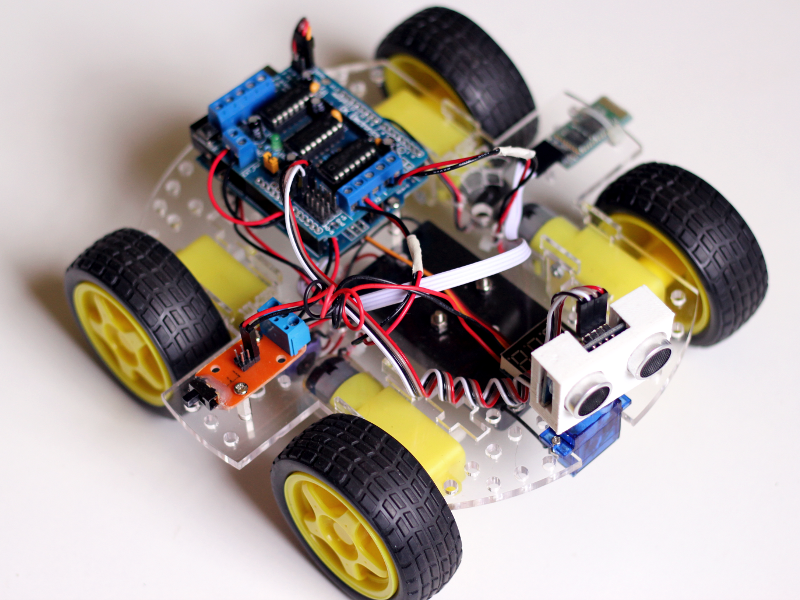
ORC-KIT is a flexible robot kit built from easy-to-find electronic components and a few specific pieces that you can manufacture and customize yourself. The software libraries and firmware, and every mechanical piece and circuit board designed for this project are all Open Source, so you can do all the changes you want to the layout and components to fit your needs.
You will require a 3D printer and a laser cutter to make the robot-specific pieces, but if you are like me and don’t have such machines, there are always hackerspaces or companies nearby that offer laser-cutting and 3d-printing services.
There’s a small blog post I wrote briefly explaining the motivation and history behind this project if you want to know more.
Everything is Open Source, so be wild and have fun with it!
Main Features
- 4WD (4-Wheel Drive) design (although you can change this if you want!)
- Supports different power/energy options out of the box (no modifications needed for this!)
- Allows easy expansion and customization (You can even use standard construction-kit pieces!)
- Demo firmware available (and a free Android app for remote control over Bluetooth)
- Open Source; everything can be customized, and if anything breaks you can make the replacement parts yourself!
How Do I build one?
You’ll find all the designs and software in the project’s Git repository which includes an instructional 2-page pamphlet that doubles as a reference guide. If you are an experienced robot builder you can study the files and modify the layout before you laser-cut the “frame” so it accommodates your preferred type of motors, sensors, controllers, etc, but I’d recommend you to read the rest of this page so you can see an example “vanilla” build (that is, a build done without customizing or modifying the parts and pieces).
Here I will focus in building a version with the basic recommended parts plus the optional Bluetooth module. Some of this information is already contained in the instructional sheet, so it might be a good idea to print it and use it as a reference while you build your own.
WARNING:
This “guide” assumes some basic knowledge of electronics. I’d love to make a guide for absolute beginners, but it would be needlessly long and probably pointless; If you’ve managed to get all the parts, and you understand what each one of them do, then you will probably have no problem following the instructions here. Some Google-ing may be needed, but if you enjoy learning new things and tackling a fun challenge then you’ll definitely have no problem with this. Oh, and print the 2-page instructional guide from the repo!
Step 0: Choose a power configuration
A good first step is to decide the type and amount of batteries to use. This of course will depend on the electronics and hardware you will end up using, which is something you should definitely define before you go shopping for parts. We are using 6V DC motors and an Arduino (which runs at 5V). To keep everything running nice and smooth we need something around 7-8V.
In the current version of the board there are two areas for batteries: One of them supports either four AA batteries or two 18650 cells, and the other one can hold either a single 9V battery, two AA batts or one 18650 cell. This means you can have up to 6x AA batteries or 3x 18650 cells, with an optional 9V cell (if you’ve not used the second battery spot) for independently powering your Arduino and/or electronics if you so desire. I’ve summarized a few possible configurations in the table below:
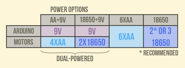
A “Dual powered” config can get a bit messy to wire and setup, so for a starter build I’d recommend choosing a single power supply for everything. For an Arduino-based build with our 6V motors and a few sensors, either 6x AA rechargeable batteries (6*1.2V = 7.2V nominal voltage) or 2x 18650 cells will work (2*3.7V = 7.4V), but I’d go with the later option because 18650 batteries are just wonderful. They are rated 3.7V, but freshly charged cells output around 4.2V and can safely be used down to 3.5V or 3.6V. This gives you an output between 6.8V and 8.2V, which works great.
It’s worth noting that if you connect the batteries directly to the motors they’ll run stupidly fast for a while but their speed and torque will decrease as batteries lose charge. The motor controller doesn’t provide voltage regulation but since it still works for our purposes (and a lot of toys behave just like that anyway) we will use it as it is. You may want to add a 2 or 3A 6V voltage regulator between the batteries and the motor driver later to achieve a more constant speed.
Step 0.5: What you’ll need.
Now that you’ve chosen your power configuration you can gather all the needed parts. The things you’ll need to laser-cut are the base plate (4mm acrylic) and the motor mounts (2mm acrylic). You’ll also need to 3D-Print the sonar casing and optionally the 9V battery holder. All the 3D models and files are in the project repository.
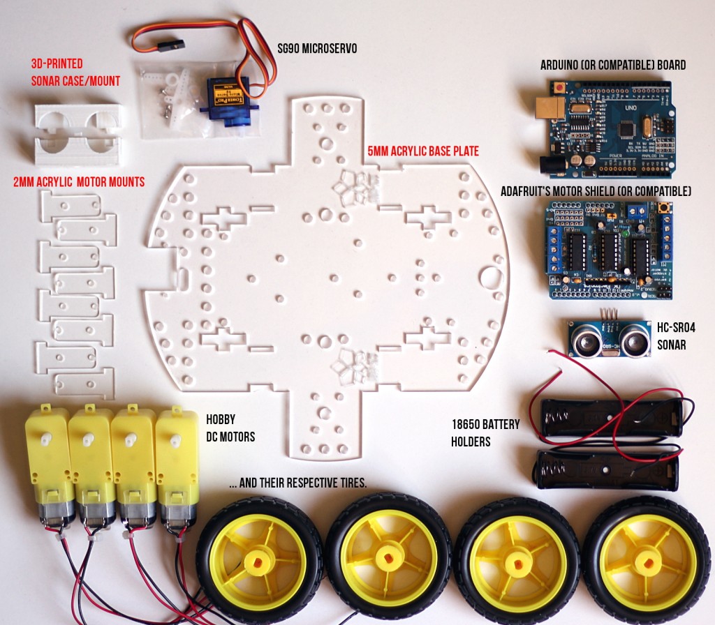
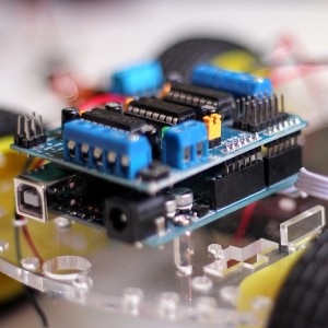
The “vanilla” ORC-KIT build uses an Arduino (or compatible) board for the brains (as hinted by the power config table) and Adafruit‘s Motor Shield (or compatible) for driving the motors. The first version of Adafruit’s Motor Shield became so insanely popular that a lot of clone boards started appearing and it’s really easy to find them nowadays on the cheap (In fact the one I’m using is a clone board and didn’t know until I researched the board). Adafruit has done an incredible job updating their fabulous shield but I’ve not tried their new version so I can’t guarantee that it will work with my code.
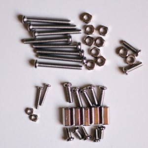
Oh, you will also need a number of screws and bolts for installing everything on the base plate.
For this build you will need 8x M3 (3mm diameter) screws either 25mm or 30mm long for the motors, a couple of 10-12mm for the battery holders, and a bunch of PCB spacers and M3 screws for the electronics.
You will also need 2x M2 (2mm diameter) 10-12mm screws for the sonar servo.
If you have some experience with electronics you can also use a proto-shield and two H-bridge drivers instead of the motor shield.
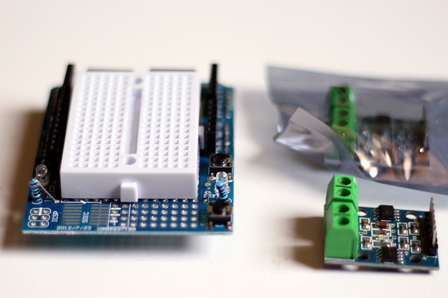
ORC-KIT’s base plate has space for two L9110S Dual H-bridges if you decide to go this way, but whle using a protoshield gives more options for adding stuff in the future, for the sake of simplicity (and because the example code is designed for this) I’ll be using my Not-quite-Adafruit’s Motor Shield for this guide.
UPDATE: I wrote another small post about using the L9110S drivers, for experience/advanced builds!
Optional stuff
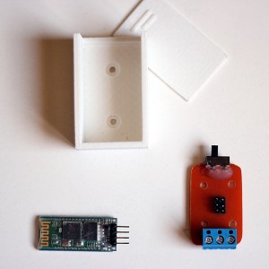
As stated before, if you decided to use a 9V battery for the Arduino you will need to 3D-print the 9V battery holder I designed for this project, and if you want to try the Bluetooth control app you’ll need a HC-06 BT module.
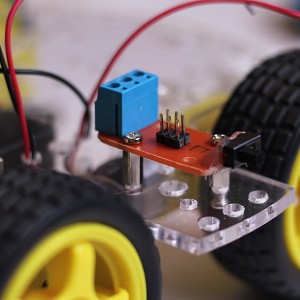
I also designed a “Power hub“; a small board with a switch that makes wiring additional stuff a wee bit more convenient, so if you know how to make PCBs you can build this simple board as well (schematic and board layout are also in the project repository).
I will only add the Bluetooth module and Power Hub to this build, as I’ve chosen to power everything from 2×1850 cells and won’t be using a 9V battery at all.
Step 1: Mounting the motors
Using the laser cut motor mounts and 8x 25-30 mm M3 screws and bolts you can now attach the motors to the base plate as pictured below:
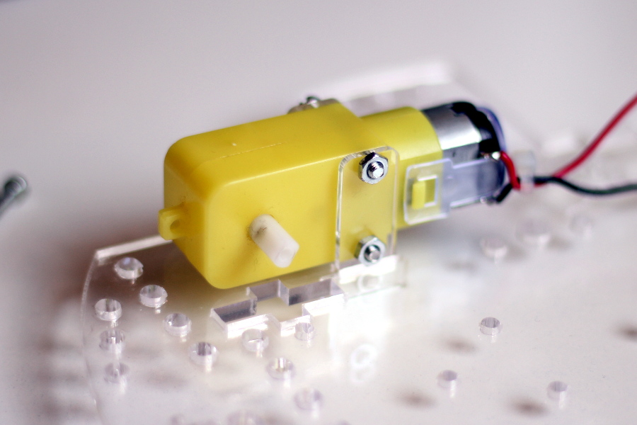
A note about the motors: They come in 48:1 and 120:1 gear ratios, which affect the output speed and torque (120:1 gives the slowest speed but higher traction, while 48:1 is faster but gives you less torque). They have the same size and footprint so you should be able to use either type of motor without problems here. Just don’t mix them up!
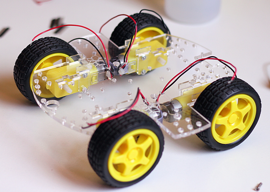
Once you’ve installed all of them you can try attaching the wheels. If they don’t fit tightly enough you can put a small bit of masking or painter’s tape perpendicularly over the shaft’s end before you insert them. This normally works great if by any reason they didn’t fit well from the start.
Step 2: Mounting the battery holders
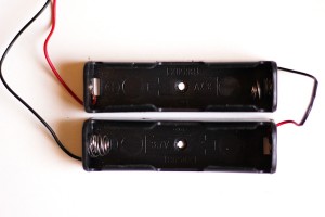
Depending on the selected power configuration you may need to combine several battery holders together, which is achieved by connecting their wires serially as shown in the picture.
Any battery that goes in the battery spot near the rear end of the robot should be mounted underneath the base platform as the Arduino board will be installed on top. We are not installing batteries on that location in this build, so I won’t be showing that here.
For the other battery spot, the holders can go either above or below the base plate. I prefer to install them underneath so I have extra room on top to mount a second “floor” for electronics, sensors, etc but this shouldn’t make much of a difference. It’s up to you to decide where the batteries will be less exposed to damage.
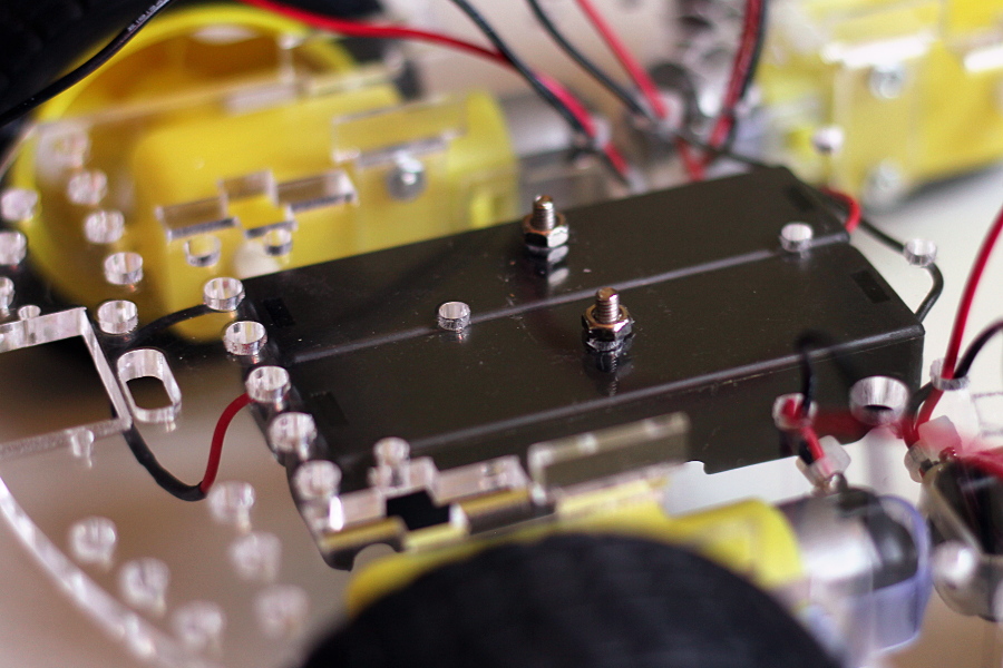
It’s a good idea to use some double-sided tape between the battery holders whenever you have to install two of them together like this, so they will act as a unit and will be set more firmly in place. I could have used a battery holder that was already made for two batteries, but when it comes to 18650 batteries single-cell holders are way easier to find (and if you want to add another cell to the robot you’ll need one of these, so why not use them for everything?).
Step 3: Install the sonar servo
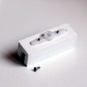
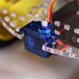
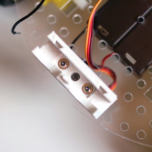
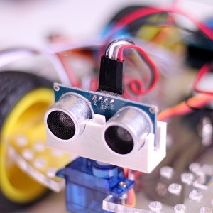
This robot uses an ultrasonic rangefinder to detect obstacles which will be held in place by our special sonar mount/case. The bottom part of the 3D-Printed sonar head needs to be screwed onto a standard servo arm as shown below. Then you will need to install the servo itself on the base plate using 2x 12mm M2 screws and bolts, and screw the sonar case + arm onto the servo shaft.
Step 4: Mount the electronic components
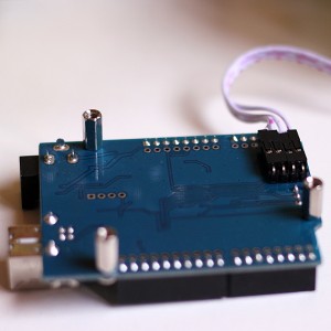
Please note that I’ve decided to use an “Arduino compatible” board and not an official Arduino. The reason for this is that whoever designed this derivative board expanded the original design and added an extra row of solder pads for connecting wires or headers next to the shield connector, and also included a small “port” with relevant communication signals for SD cards and serial devices, which is exactly what I’m going to use to easily connect the Bluetooth module. You will notice that I’ve soldered a 90° pin header row underneath the Arduino so I can attach there a cable to the bluetooth module. An official Arduino board will work, but you’ll need to solder some wires under the board to the TX, RX, +5 and GND lines to connect the HC-06 BT module.
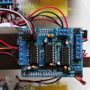
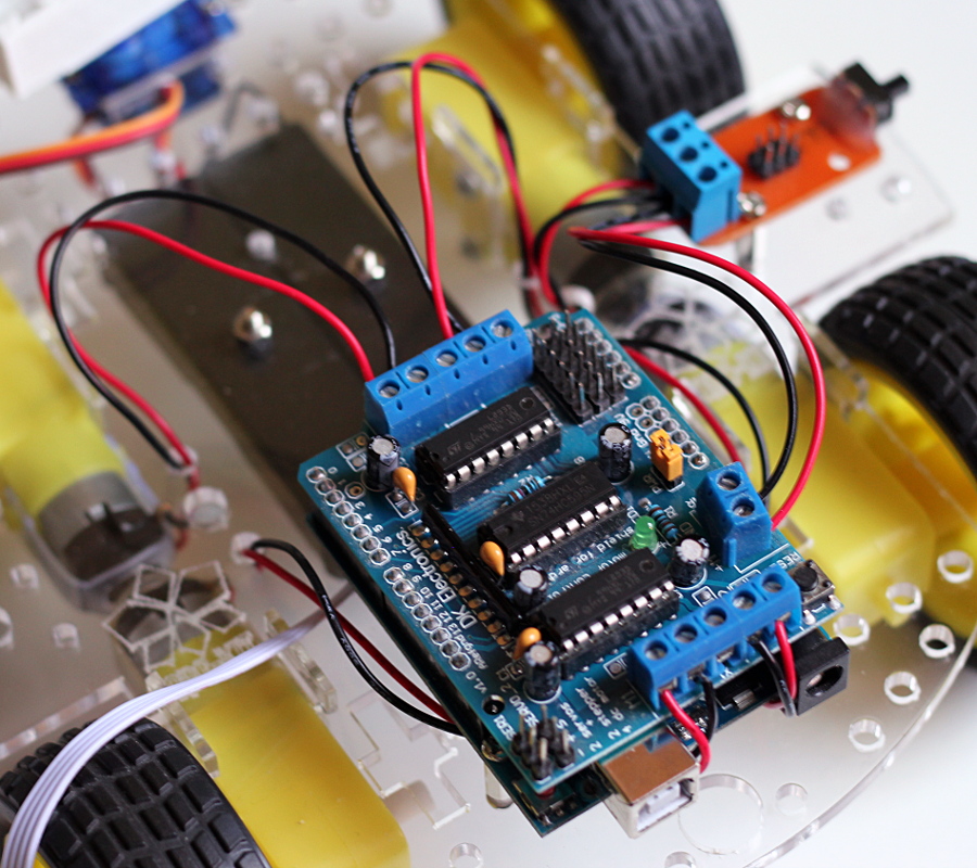
Now, using PCB spacers and M3 screws you can mount the Arduino board and other electronics. For my build this means the Arduino itself, the motor shield on top, and ORC-KIT’s Power Hub.
Step 5: Wiring everything together
There’s a handy diagram in the reference guide that pretty much sums up how everything should be connected. Of course this step will be different for you depending on what components you used, but I’ll show here what I needed to connect in this build. You can double-check everything with the reference guide, which I recommend you to check every so often to gain a better understanding of this step.
Step 5.1: Connecting the power supply to the electronics
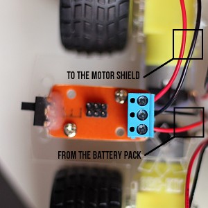
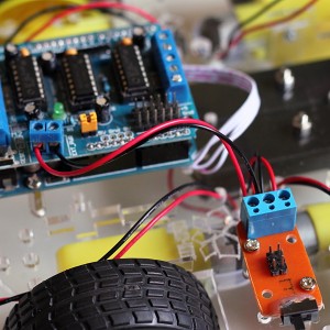
First, you need to connected the 2 wires from the battery holder to the power hub. The black cable (negative) should go to the middle terminal of the block, and the red (positive) one should be connected to the bottom pin (which is the input) Then, connect 2 cables from the power hub to the motor shield; one from the middle pin of the hub to the GND input of the motor shield, and another from the top pin of the Power hub to the “M+” input on the board.
The motor shield shares voltage input with the Arduino board, so connecting it to the power supply energizes the whole thing (unless you remove the small plastic jumper on the board, which is something you’ll actually need to do if you are using separate power supplies for the Arduino and the shield).
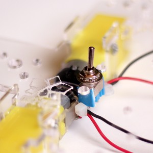
If you didn’t build ORC-KIT’s marvelous patent-pending Power Hub you can install a standard toggle switch between the motors, or in one of the “wings” of the base plate. There are 4 spots in total where you can place a switch.
Once you’ve installed it, you only need to connect one of the wires from the battery holder directly to the motor shield and the other one from the holder to the middle pin of the switch, and then a cable from either of its remaining pins to the board. This is also shown in the reference guide with greater detail. As I haven’t followed this configuration here I don’t have pictures to show of the actual connection.
Step 5.2: Connecting the motors to the shield
For this step don’t worry too much about the “polarity” of each motor. This will mostly depend on how you soldered the cables to the motors themselves, so we will later use an Arduino sketch to determine if we have connected the motors correctly. For the time being just wire the right-side motors to the spots labeled “M2” and “M3” on the controller, and the left-side motors to “M1” and “M4”.
Step 5.3: Connecting the sonar servo
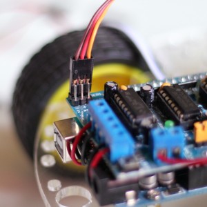
The servo is what will make our sonar move, allowing our robot to “turn its head” to either side. There are 2 spots for servos in one of the corners of the motor shield. Connect our servo to the first one, with the brown (or black) cable wired to the “-” pin of the connector.
Step 5.4: Connecting the actual sonar
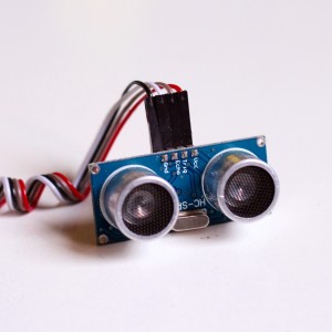
Place the HC-SR04 sonar module in the 3D-printed piece we attached to the servo and connect a 4-pin cable to it. This cable will also go to the board.
The Motor Shield uses most of Arduino’s pins, but it exposes the 6 “analog” pins (A0-5) for whatever we want to use them, and they can also be configured as digital inputs or outputs. The connector in the shield also has plenty of +5v and Gnd connections, so we will use them to hook our sonar to the board.
A cleaner and better look at the connections can be found in the reference guide but you can also use the pictures above as extra reference material.
Step 5.5: Connecting the optional Bluetooth module?
I’m using the handy extra port of my Arduino-compatible board to connect the BT module and I’ve already attached the cable earlier, but I won’t be connecting the module immediately to the board because the Arduino board will refuse to communicate with the PC when the BT module is connected (it uses the same pins). This is important to remember as you’ll need to unplug the BT module whenever you want to make changes to your robot’s code!
Step 6: Actually testing everything
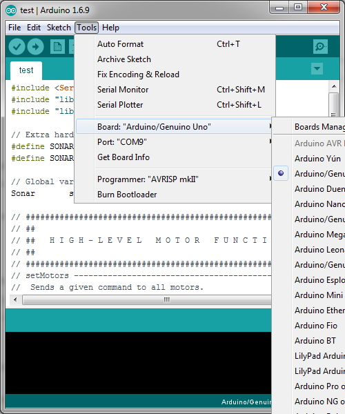
Download the Arduino programming environment and whatever drivers your Arduino needs. The driver may differ between Arduino-compatible or derived boards, but they are normally either the well-known FT232R IC, or the increasingly popular CH430G chip. Google the driver for your Operating System. My arduino-compatible board uses the CH430G chip, for instance.
The official Arduino boards use a driver that is included with the programming environment.
Once installed you should make sure the Arduino IDE detects your board, and in my case despite not being an official board, is 100% compatible with the Arduino Uno, so that’s what you need to select from the list.
I recently updated the project files so you can import the Arduino examples and code as a library from the Arduino IDE. Click “Sketch->Include Library->Add .ZIP Library” and you’ll be prompted to select either a ZIP file or a folder. Browse to the “arduino\ORC-KIT” folder from the project repository and it should import all the small libraries I wrote and the example sketches. You will find them now in “File->Examples->ORC-KIT Starter“.
To compile and run the new version of the code you’ll also need the TimerOne library, which you can install either from within the Arduino IDE (Sketch->Include Library->Manage Libraries…) or from its github repo.
We will begin with the “test” example sketch, but before you even attempt to download the code to your board I advise you to place the robot on your desk near your computer sitting on top of a small stable object that “lifts” it from the ground. When you transfer this sketch to the board the robot will immediately “center” the sonar head, and will start reporting over the USB port the distances to obstacles as read by the rangefinder, but more importantly, it will start spinning the wheels forward like crazy!, so unless you want it to go wild over your desk and anything you have there while you try the code, you better find a good “stand” that suspends the wheels above all surfaces.
If after downloading the sketch your robot’s wheels are not spinning, double check the connections and make sure that you have batteries installed and the power switch is toggled ON.
if the wheels spin, the first thing we want to do with this sketch is check if they are going in the right direction. If one or more wheels are going backwards swap the corresponding red/black motor wires in their assigned “M” port on the controller board.
If the sonar head is not looking exactly forward, unscrew the sonar mount with the servo arm, rotate it so it will face straight, and attach it to the servo again.
Now without disconnecting the Arduino from your PC, open the Serial Monitor (Tools->Serial Monitor) in the Arduino IDE and you should see the output of the sonar being displayed on your screen. Put objects in front of the sonar and should report the distance to them with reasonable accuracy:
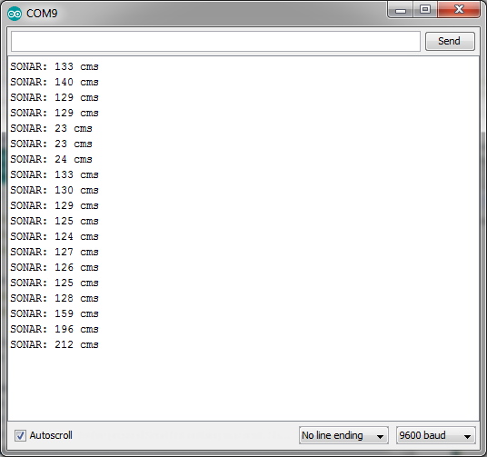
Once everything is working you can study the test sketch code and make your own firmware for the robot!
We will go one step ahead and remote control our robot via Bluetooth using an Android smartphone with the ORC-KIT’s sample BT app.
Step 7: Remote-Controlling our robot!
Step 7.1: Downloading the firmware.
Open the bt_remote sketch from project repository and download it to your Arduino board the same way you transferred the test sketch before. Remember to disconnect the BT module from your board before connecting the Arduino to your computer. Once you’ve downloaded the firmware to the board, connect the BT module again and your robot should sit still doing absolutely nothing (it’s actually waiting for commands!).
Step 7.2: Connecting the BT Module
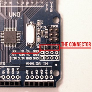
Then we need to connect the Arduino board to the BT module. In Regular boards the serial pins RX and TX are D0 and D1, respectively, but as stated before, in my Arduino-compatible board these pins are mirrored in a connector right by the bottom edge, where I soldered a header.
You will need to connect RX, TX +5V and GND to the HC-06 module in this way:
Arduino TX --- > HC-06 RX
Arduino RX ----> HC-06 TX
Arduino +5V ---> HC-06 Vcc
Arduino Gnd ---> HC-06 Gnd

Step 7.3: Downloading ORC-KIT’s BT Sample App
Unfortunately the app currently needs to be sideloaded manually. I may eventually upload it to the Google Play store but for now it’s on my server.
To sideload the app go to the Security Settings in your phone and check the “Unknown sources” option. Then follow this link or scan the QR-Code with your device to start the download. In some phones after the download is complete you can go to your Downloads folder and install the APK directly from there, while in others you’ll need an app like ASUS File Manager to navigate to the Download location and proceed with the installation.
IMPORTANT: Current App version is 1.2.5 It has been updated to support the new setCursor() function from the radioctl example code, and a bug has been fixed that makes it work on more devices now, so if you downloaded the previous version you’ll need to download it again.
Step 7.4: Connecting to the robot.
Before you run the app you’ll need to pair your phone with the robot. Enable Bluetooth and go to the Bluetooth Settings to Scan for devices. The HC-O6 module should be in the list. The default passcode (if required) is normally 0000 (Try 1234 if it doesn’t work). Once you’ve paired with the module you can run the app and click the connect button (right below the “X”).
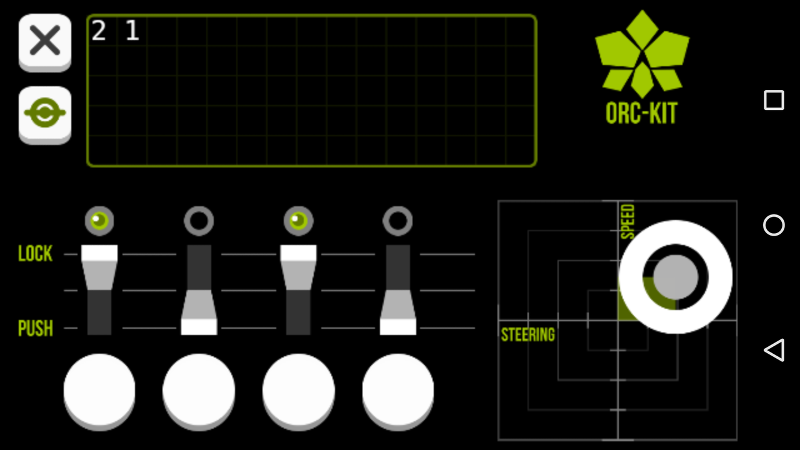
It may take several attempts to connect, but if it’s not working for you after 2-3 attempts I’d advise you to check the wiring again and make sure you’ve successfully paired the HC-06 module to your phone before.
If successfully connected you should be able to control your robot with your phone!
The small screen in the app as well as the 4 buttons don’t do much “out of the box”, but you can modify the bt_remote sketch to make the robot react to them and send information to the app.
Reading the buttons in the sketch is done with ORCRadioControl.getButtonPressed(n) while sending data to the screen is done via the ORCRadioControl.write() methods, Starting from the latest update to the project you can also set your position in this virtual screen with ORCRadioControl.setCursor(),so you can print data anywhere you want in this 26 (chars) x 5 (lines) area.
Step 8: Adding More Stuff
From this point onward you are limited only by your imagination. The vanilla design has enough mounting points for extra sensors and hardware. There’s also designated slots for opto-switches and standard encoder wheels on the base plate that you can use to measure the speed at which each individual wheel is turning.
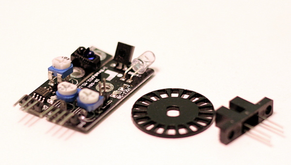
As a general rule; if the module exists, chances are that someone has already written an Arduino library for it! This makes trying new components and sensors really easy, so expanding your robot’s functionality can be a truly straightforward and fun experience.
The End?
I think this project can be a nice entry point to the fields of robotics for electronics hobbyists, and a solid foundation for experienced builders to create their own designs. With some assistance it can also be an excellent learning experience for someone who has not built a robot before and it can easily become a classroom project for a whole programming course.
I’d be happy to see people building their own ORC-KIT-based robots, or making modifications to the design.
If you happen to build one let me know!
